We will continue our journey into building a quadcopter by working on the flight controller circuit.

The flight controller that we will be using is the Acro Naze32 Flight Controller ($31). This controller requires a little assembly prior to using because it comes in parts. The surface mount parts are on the board but the headers need to be soldered to the circuit. 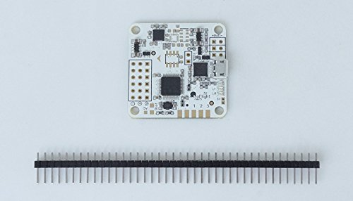
The board comes with a straight or angled connector. It is confusing which you want to use. If you get the board without the barometer module it is recommended to use the straight connector. If you get the board with the barometer chip then the angled connector is probably best so that you can put a GPS unit in the same space on top of the quadcopter.
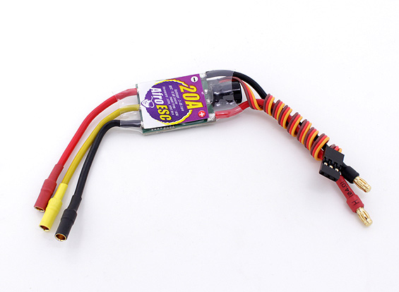
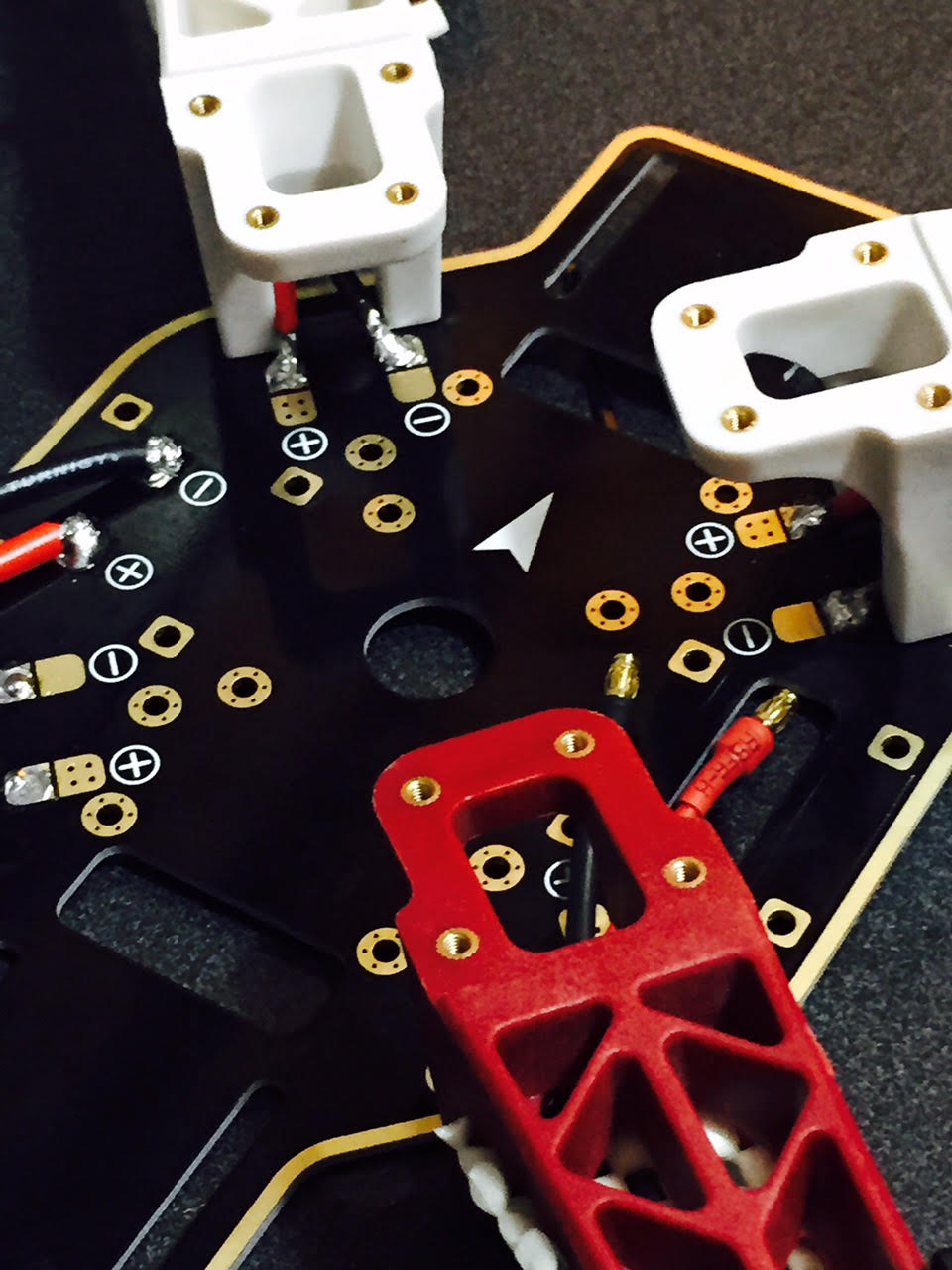
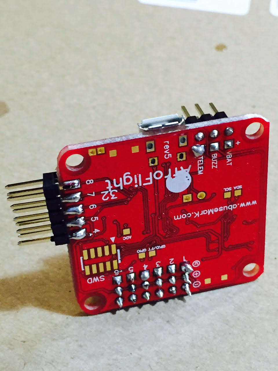
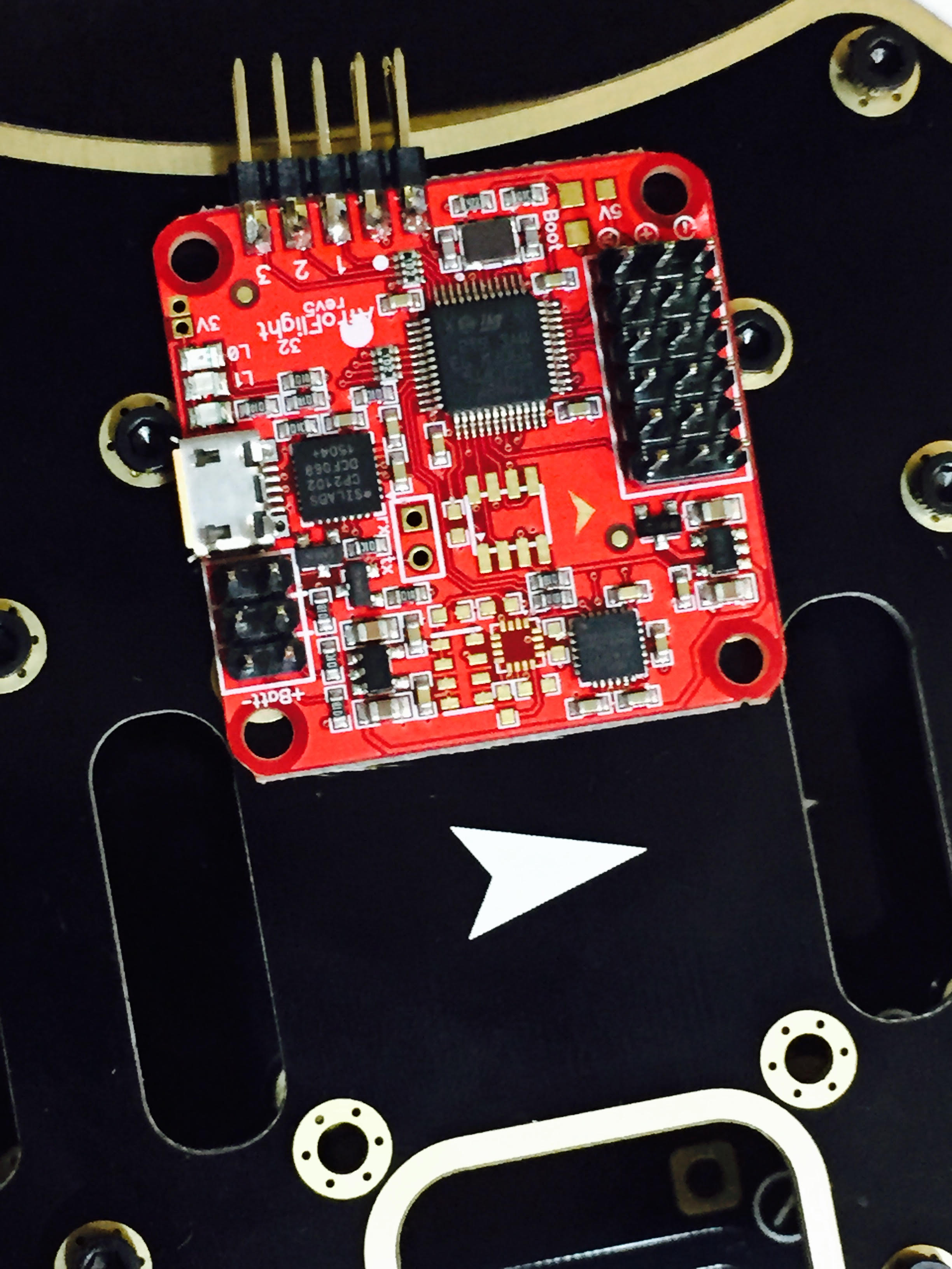
In my opinion, the design of the board is counter intuitive and has some design flaws. The kit comes with three connectors that need to be soldered onto the board. The two headers that go through holes on the board are relatively easy even though one of the connectors is millimeters from a surface mount component. What makes no sense to me is the gold connector that you have to side mount pins to. A connection like this typically is easy to mess up and break under vibration. Why put an edge connector here and not put through holes to solder? The pin towards the middle of the board is close to three surface mount components. Overall, I think that the design is somewhat silly. Why ship extra headers at extra cost but skimp on board size and not put through holes for higher reliability? The connector that I am openly ranting about is the connector shown on the far left on the picture below (connected to pins 4,5,6,7, and 8).
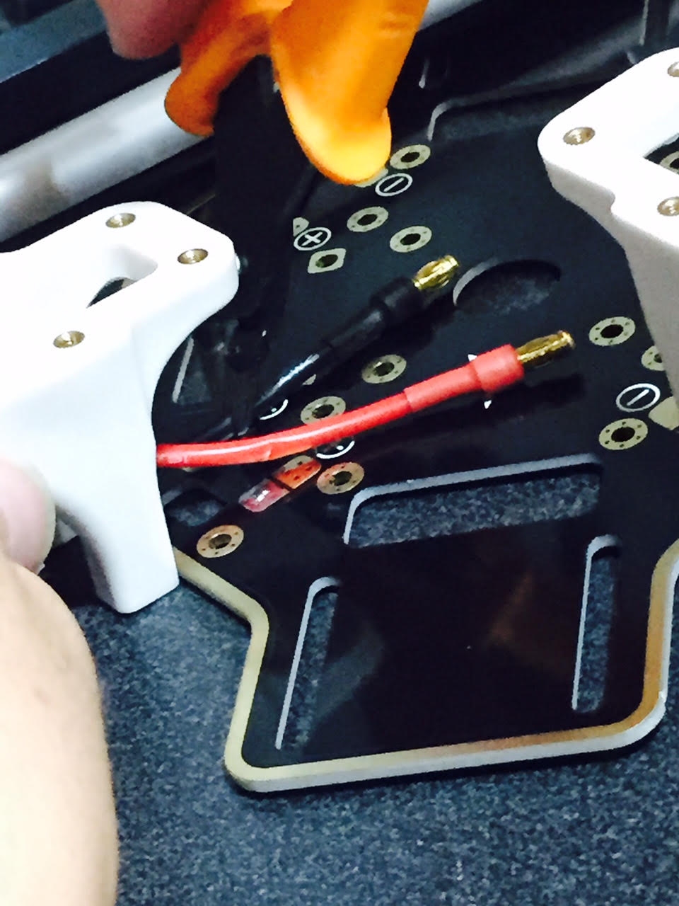
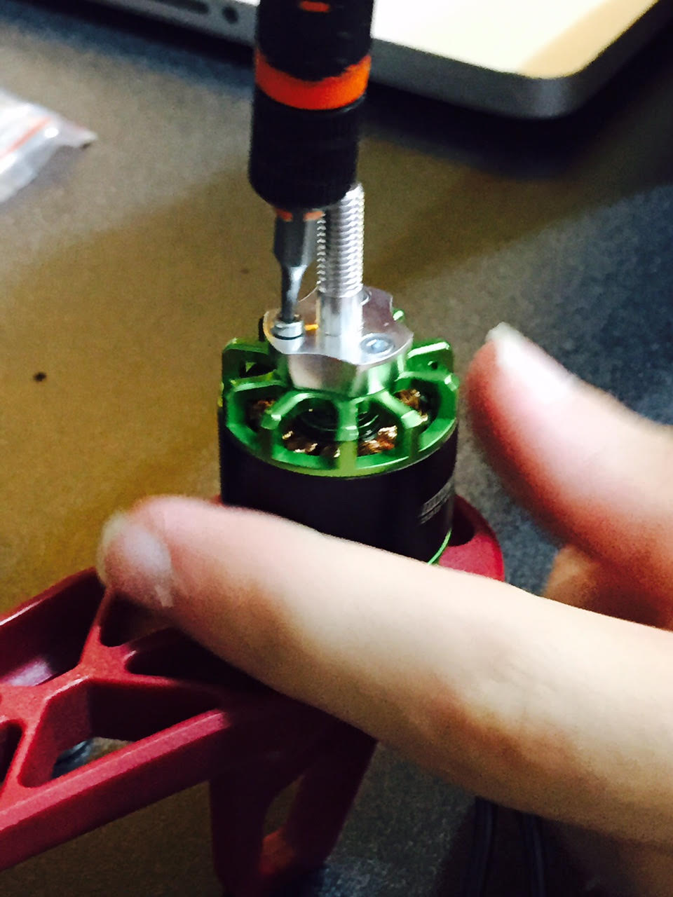
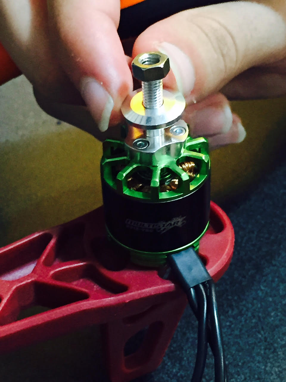
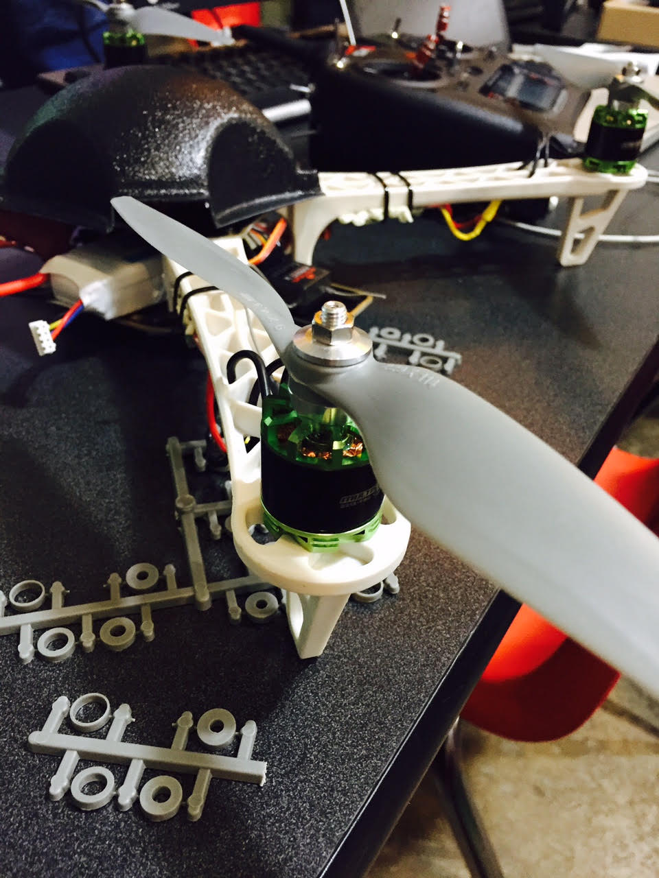
The next step is to lock down all of the screws mounting the arms to the Q450. This is relatively simple and requires a 2.0mm allen wrench. Once these are locked down we screw the prop mounts onto the motor with a 2.3mm allen wrench. The two photos below show the screws going into the motor then the prop spacer and nut to hold the prop.
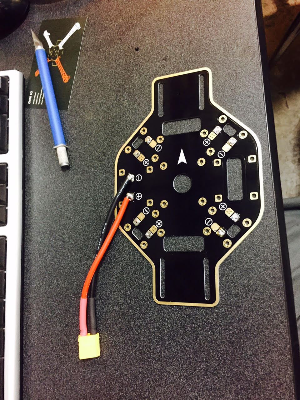
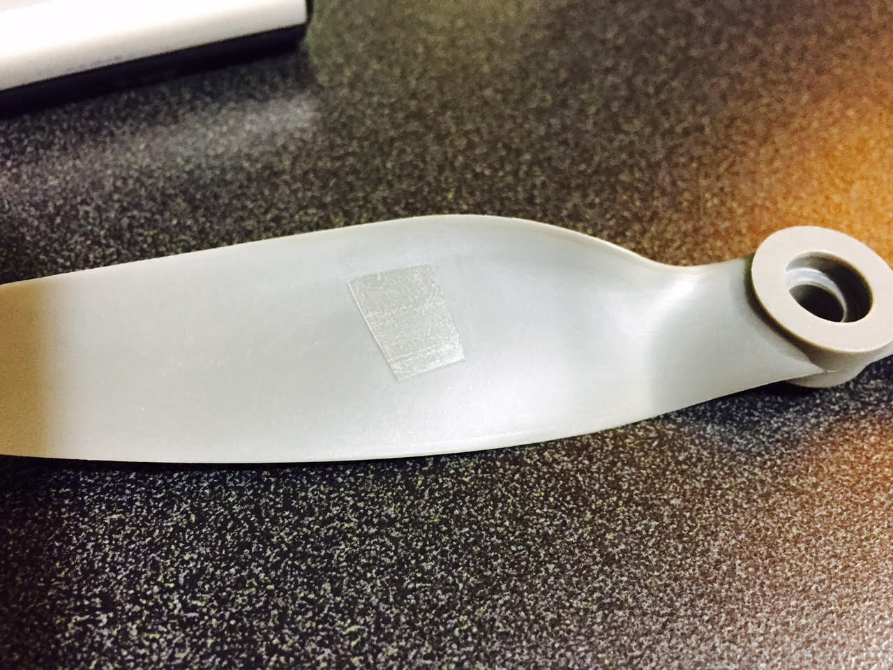
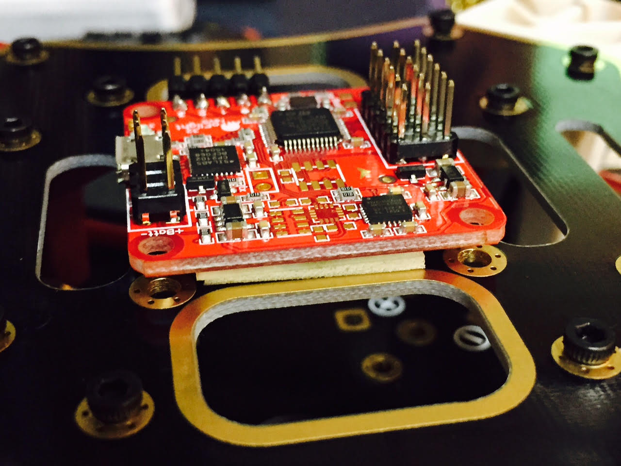
The next step is to mount the flight controller to the quadcopter assembly. The assembly has an arrow on top pointing to the direction of travel. The circuit board also has an arrow pointing to the direction of travel. We are going to mount the flight controller board on top of the quadcopter using double sided tape (we could use screws and spacers if desired because the holes are on the board and on the quadcopter). If you use screws and spacers you need grommets to reduce vibration. The double sided tape tends to dampen vibration and keep the system from changing during flight. It is CRITICAL that you use enough tape to isolate the electrical components and the board. It is also CRITICAL that the arrows align with each other. This keeps the software and remote controller aligned. Moving the board off axis will cause imbalance in the motor controller and flight controls.
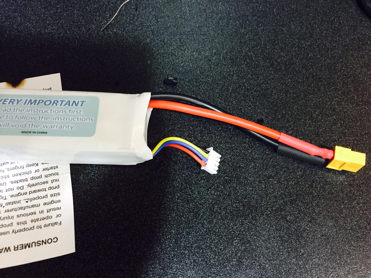
Once we have the flight controller mounted, we can mount the battery between the two layers. This is done with a velcro strap to allow for quick release. We loop the strap through the two rectangular holes on the bottom board.

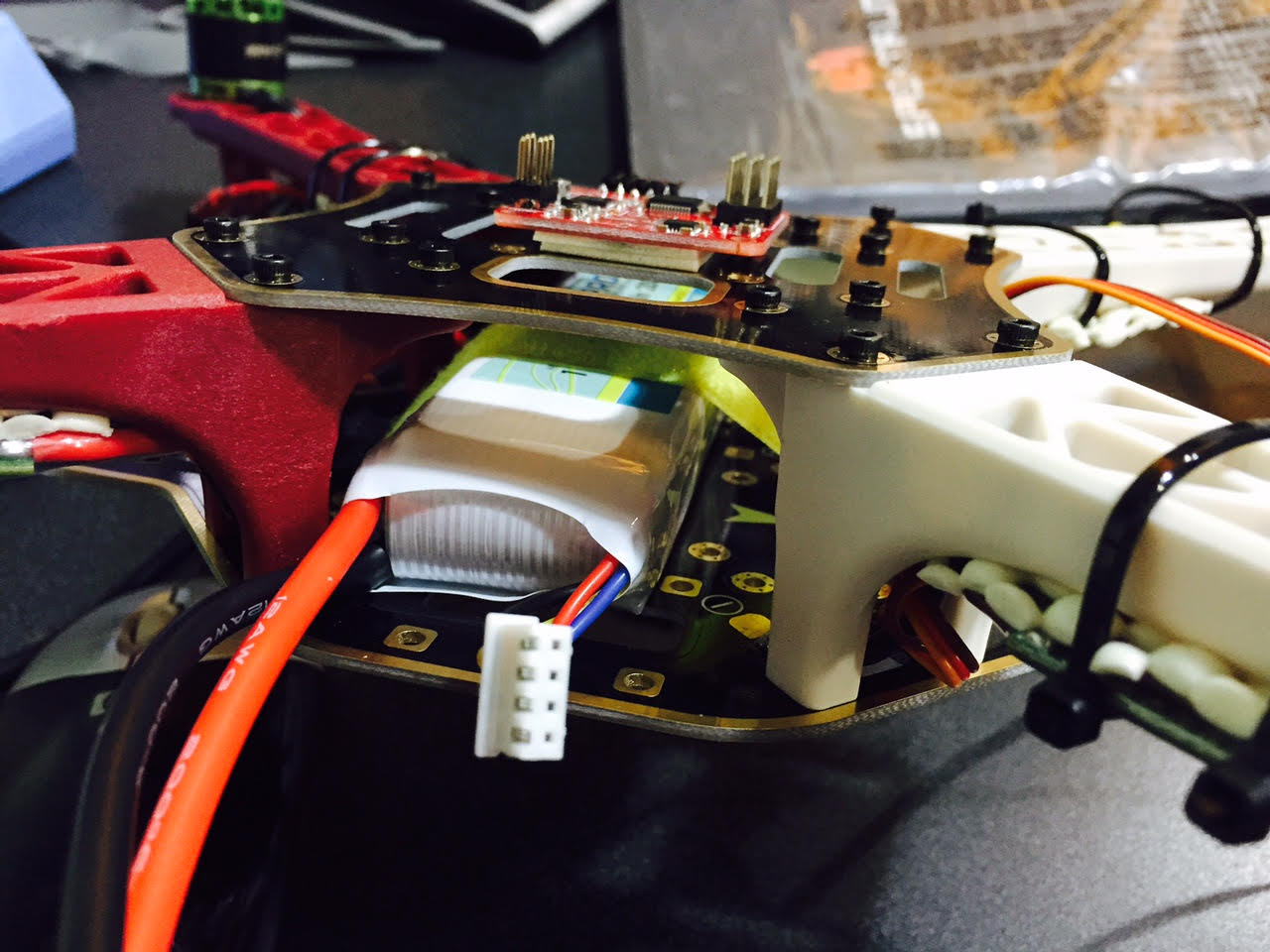
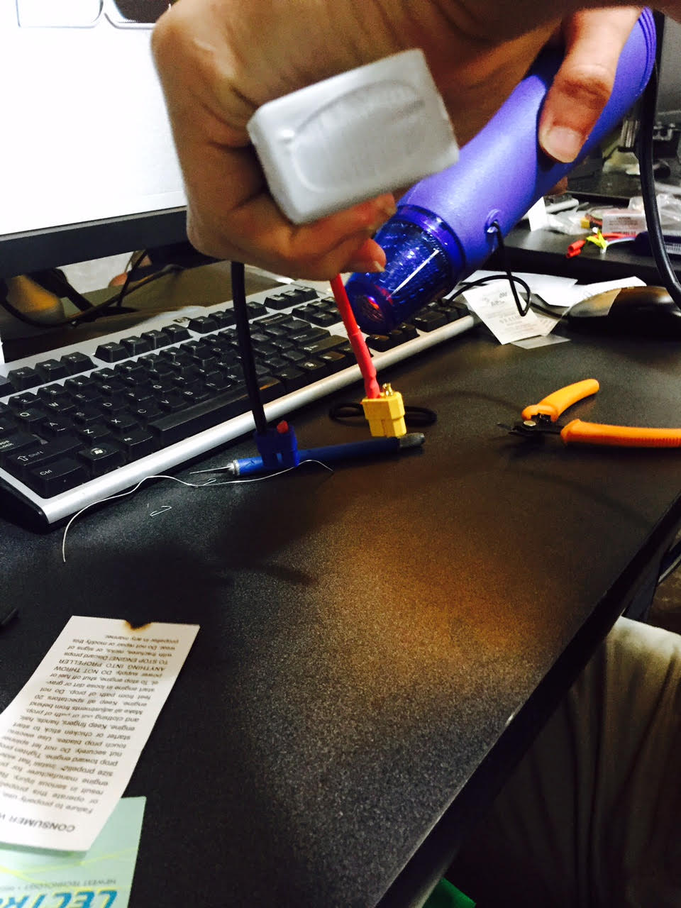
The next step is a little difficult. We need to take the middle wire (red wire) from the 3 pin connector coming off the speed controller and pull it out. We don’t want all four speed controllers providing power to the flight controller. We take the middle pin out from three of our speed controllers and cover them with shrink fit tubing. The reason why we use heat shrink rather than cutting the wire is to have redundant systems to use in the future. We can always take the tubing off and put the cable back into the connector.

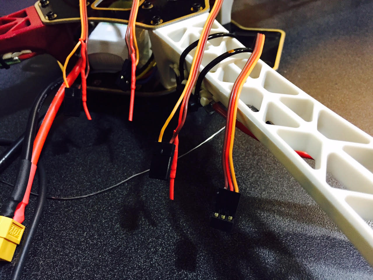
Now that we have three of the connectors modified, we can plug these connectors into the flight controller.
In the class we took a diversion and downloaded the baseflight-configurator using Google Chrome Store. This is done by searching for baseflight-configurator and installing the plug-in. Once the plug-in is installed, launch it and install the USB driver for the computer that you are using. Once this is installed you should be able to connect to the flight controller from a USB to mini-USB connector.
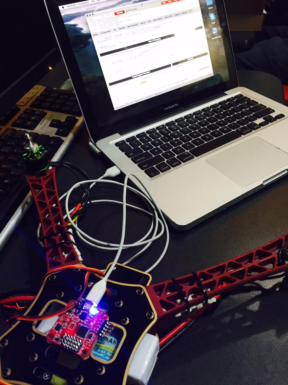
With this we have a connection to the flight controller from our laptop. If you click on the connect with the port configured to be at 115200 speed you should get a green Disconnect button rather than a red Connect button. As you move the quadcopter around you should see the motion mirrored on the laptop.
The first thing that we need to do once we have the baseflight-configurator running, we need to update the firmware and flash it to the controller. We download the firmware from github then flash it to the controller.
From this we go into the configurator and setup things like motor rotation direction, throttle max and mins. Make sure all features are turned off. We then save and it updates the flight controller firmware.
The class instructions starting at page 113 have screen shots of all of these configurations along with explanation of all options and selections.
One side discussion was that a mobius 1080p camera ($82) is a good add on. It allows you to record a flight and does not add much weight to the quadcopter.
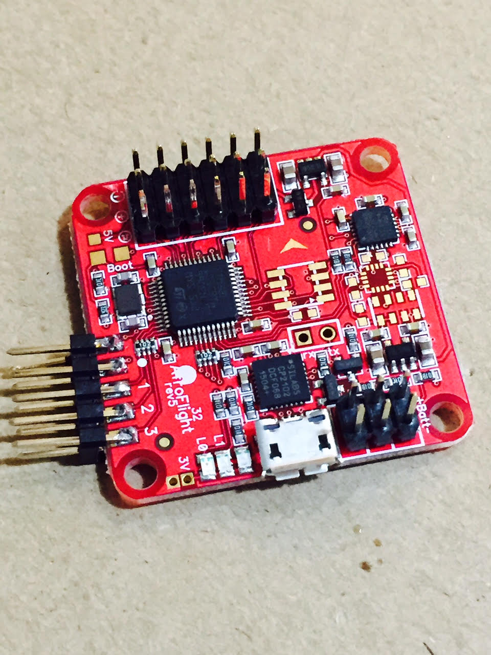
Once we have the software operational, we can connect the speed controllers (and thus the motors) to the flight controller. Looking at the configuration diagram for a Quad X configuration we notice that the bottom right motor is channel 1, top right is channel 2, bottom left is channel 3, and the top left is channel 4. This corresponds to the pin block at the front of the flight controller (front being where the arrow is pointing). The numbering starts from the right side with pin 1 and goes to pin 6 at the left. The orange cable is the signal, the red pin (only connected via channel 2) is power, and the brown wires are ground. You can verify this by looking next to pins 6 and see the “-“, “+”, and square wave on the circuit board. In the photo below we have the speed controllers plugged into channels 1, 2, 3, and 4 with channels 5 and 6 unconnected.

The next step is to plug back into the laptop and test the rotation direction of the motors. By going into the motor testing tab we can energize the motors and rotate them at different speeds. This allows us to test the direction of the motor rotation and reverse the red and yellow wires going to the motor to have them rotate in the direction that we want.
The cool thing at this point is that we have a working quadcopter. We have a battery pack that is communicating to the flight controller. The flight controllers are pushing power to the speed controllers thus turning the motors. The only thing that we are missing is the rc controller to control motor speed and flight. We are using the laptop as the rc controller for calibration.
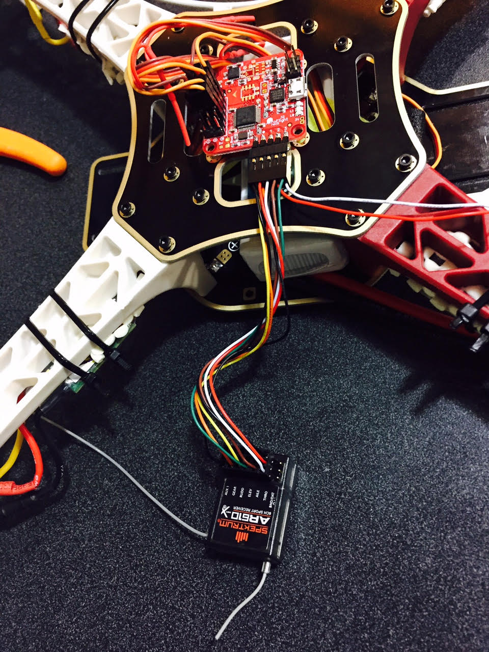
The next step in the class is to get your rc transmitter paired with the on-board receiver. Given that we had a Spektrum transmitter and receiver, it was different from everyone else. For ours we had to follow the directions in the Spektrum manual. Page 10 shows how to bind the receiver with the transmitter. We used the bind plug method (Binding Using the Receiver and Receiver Battery). We plugged the bind plug into the bind section of the receiver and unplugged connector 2 from the flight controller and plugged it into the receiver. We put the transmitter into bind mode and waited for it to sync with the receiver. Once this one done, the transmitter acknowledged the connection and we could power down the receiver.
The receiver has labels on the connectors. Looking from the bottom with the printing on the left, the bottom row is the bind/dat row. The next row is labeled Thro which correlated to channel 1. The Aile (aileron) is channel 2. The ELEV is channel 3. The RUDD is channel 4. The GEAR is channel 5. The AUX1 is channel 6. Once we map these to the receiver, we need to program the transmitter appropriately.
With the receiver connected, we power on the quadcopter by plugging in the battery (while connected to the laptop) and can calibrate the rc transmitter so that the controls min out at 1000 and max out at 2000. This is done for the four channels that represent thrust (THRO), pitch (elev), roll (aile), and yaw(rudd). By moving the controls on the transmitter we can see the controls change on the computer. The motors should also spin while you are playing with the controls. You should be able to verify the different motors spinning as you adjust the controls.


At this point we have a transmitter that communicates to the receiver. We have a receiver that is communicating to the flight controller. We also have a flight controller that is energizing the speed controllers and making the motors spin. The only thing that we are missing is a cover to protect our electronics and propellers.
The cover that we are using is a cover printed by the instructor. The cover is ABS so it is easy to modify with drill holes and cut excess edges off. You can then tape or velcro the top to the quadcopter frame. The instructor puts his receiver taped to the top cover. We are going to put our receiver between the two decks with double sided tape attached to the bottom. You can operate without a cover but your electronics are exposed and hitting the ground could get moisture or dirt into your circuit board.
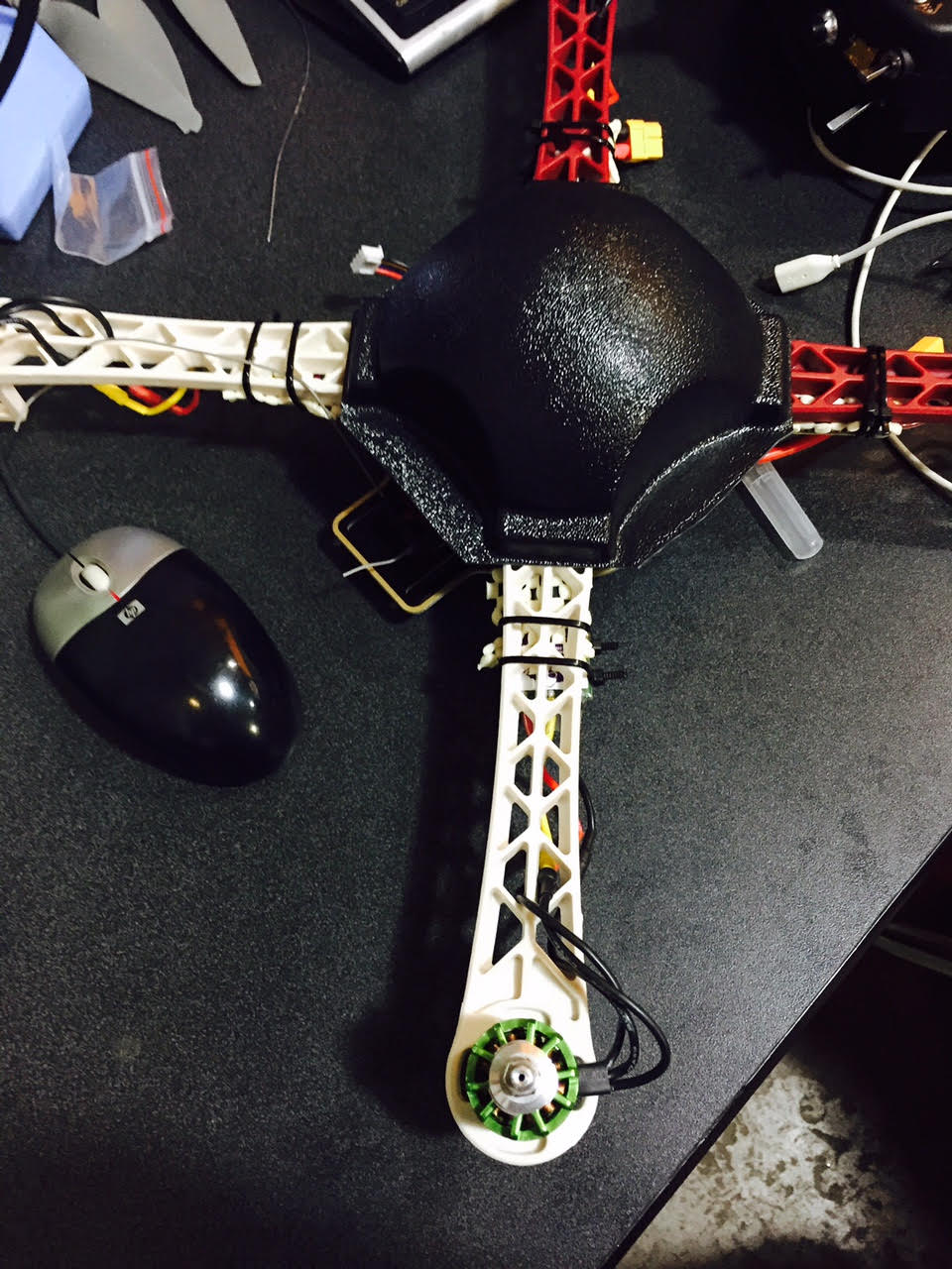

We will use a dremel tool to route out parts of the cover to allow it to fit on top of the assembly and fix it to the frame using velcro.
The props are put onto the motor shafts. The rings under the quadcopter are stabilizers for the propellers to keep them from vibrating. The ring goes onto the shaft first followed by the propeller then the metal washer and metal nut. The metal washer is a bridge to protect the plastic propeller and help keep the nut tight on the shaft. Use a wrench to tighten down the nuts before flying every time that you fly. During flight, half the nuts are trying to get tighter and the other half is trying to get looser.
With this we have flight! Plugging in the battery and powering on the transmitter allows us to fly our new quadcopter!
Now that we are at the end of the class, let’s review the overall cost. The class itself was $345. This cost covered about half of the cost of building a quadcopter. The overall cost to build this system from scratch is just over $700.
The up front costs for this class are:
- $300 – rc controller
- $43 – Lectron Pro 11.1 volt Lithium Ion Battery
- $45 – Prophet Sport Li-Pro 35W Peak Battery Charger
- $345 – class fee
total cost: $733
Included in the ($345) class you get
- $4 – clear electrical tape
- $2 – solder
- $18 – apc composite 9×4.5 MR (2) and MPR (2) props
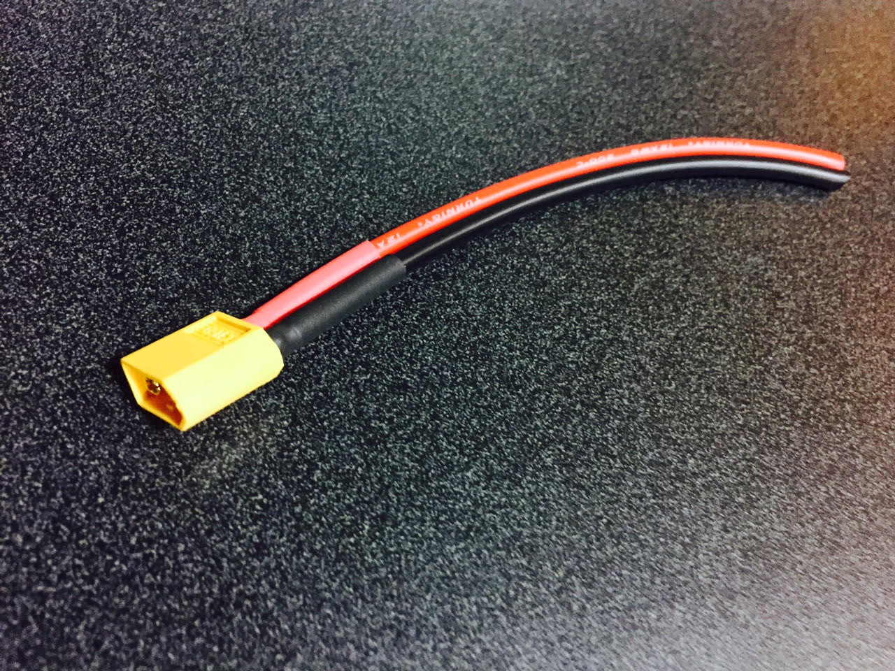
- $6 – XT60 connectors
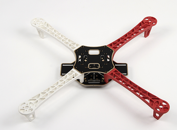
- $13 – Diatone Innovations Q450 V3 quadcopter frame
- $21 – Afro ESC 20A speed controller (4)
- $3 – zip ties / velcro / double sided tape
- $13 – non-adhesive shelf liner
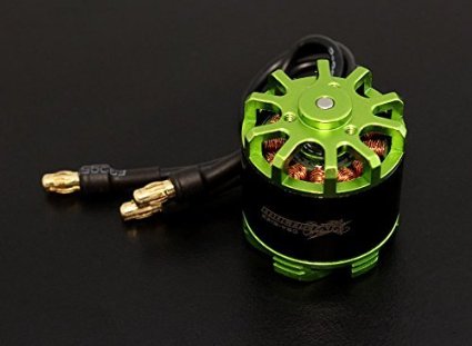
- $220 – Multistar 2213-980 14-pole outrunner motor (4 at $55 each)
total in parts: $300 that comes with the class
optional components are:
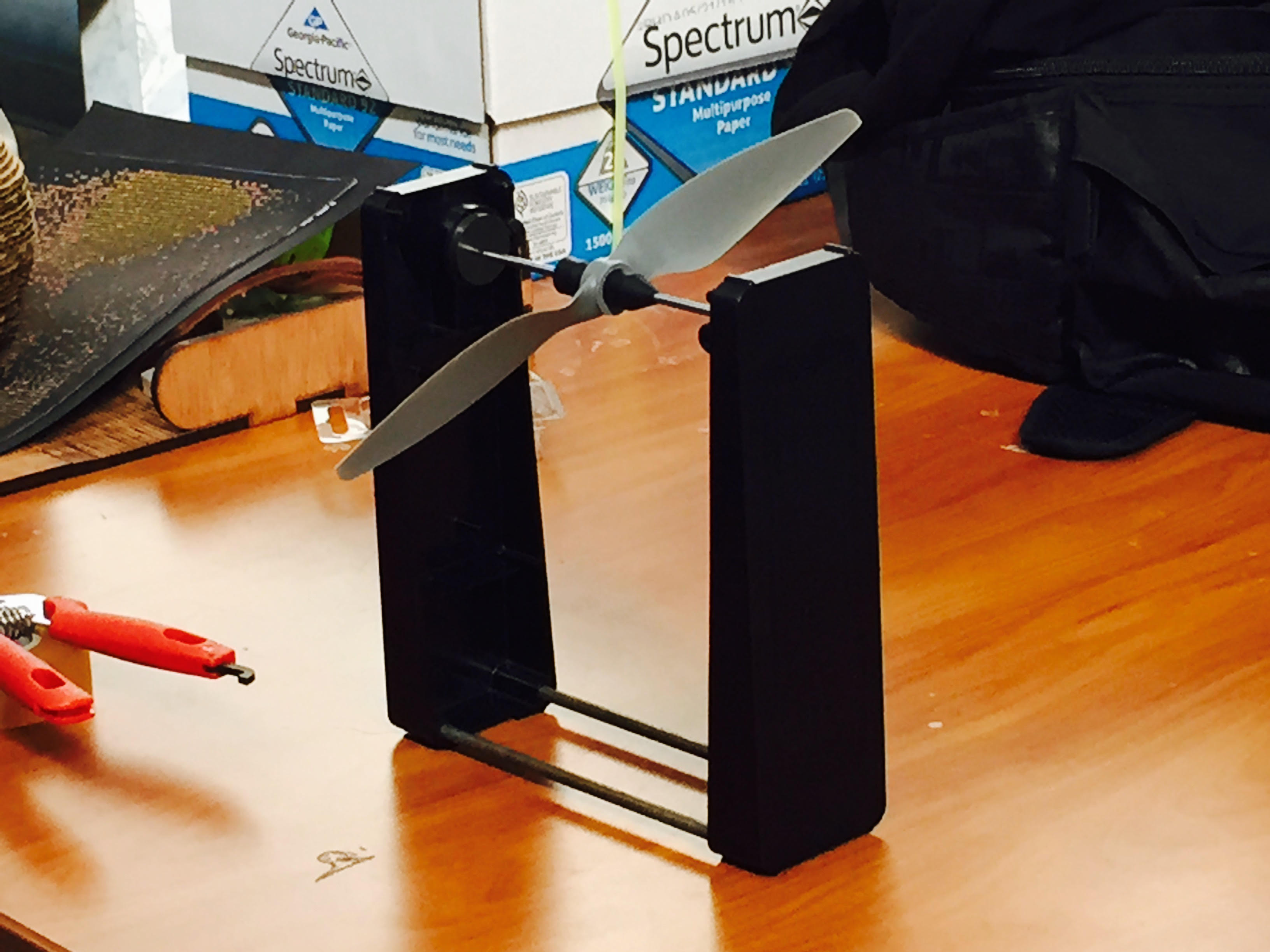
- $20 – prop balancer
- $8 – lipo battery monitor
- $60 – watt meter
Overall, this was a very good class. It was good talking about the theory and practical ways of building a quadcopter. The class does not focus on flying but does talk about when, where, and how to fly. You are on your own to learn how to fly and repair the quadcopter as you crash while learning.