Adding programming languages to Raspberry Pi

One of the nice things about a Raspberry Pi (any version) is the ability to program from the command line or a development environment (IDE). In this posting we will look at some of the programming languages that are pre-installed with the default operating system and how to add a couple more as desired.

Python

Python is a relatively simple programming language. From https://www.python.org/doc/essays/blurb/ the language is

“Python is an interpreted, object-oriented, high-level programming language with dynamic semantics. Its high-level built in data structures, combined with dynamic typing and dynamic binding, make it very attractive for Rapid Application Development, as well as for use as a scripting or glue language to connect existing components together. Python’s simple, easy to learn syntax emphasizes readability and therefore reduces the cost of program maintenance. Python supports modules and packages, which encourages program modularity and code reuse. The Python interpreter and the extensive standard library are available in source or binary form without charge for all major platforms, and can be freely distributed.”

What this means in a nutshell is that Python is easy for building complex things from simple constructs. You can create a description of something like a vehicle and assign a number of wheels to. You can write routines to drive each wheel and potentially turn each wheel simply and easily. The modules and packages allow you to take work of others and use them without having to write everything for yourself. Documentation on Python can be found at https://docs.python.org/3/contents.html and chapter 6 details how to define and import modules https://docs.python.org/3/tutorial/modules.html# so that you can leverage the work of others or share with others.

To test what version of Python is installed on your system, open a command prompt and type

python –version

The command prompt should return a version of level 3 or higher with a sub-version following the dots. To execute a program you can type python to invoke the interpreter and type python commands into the interpreter. The code will be executed as you type it.

The command print() prints to the console what is between the quotes. The exit() command exits the interpreter and takes you back to the command line. Alternatively, you can enter the print and exit commands into a file and type python filename to execute the stored program. Traditionally a python file uses the “.py” extension so if we called our file Hello.py we would type

python Hello.py

It is important to note that capitalization is important on a Linux (or Raspberry Pi) system so make sure the file name and what you load into python match exactly. It is important to note that Hello.py and hello.py are two different files.

C and C++

The C and C++ programming languages are a little more structured than Python and is more useful when trying to define something as an object rather than a thing. If, for example, we wanted to describe a vehicle and the vehicle could be a bicycle, a tricycle, a car, a boat, or a rocket ship we could define how to make it go or make it turn using a common subroutine. The subroutine could then determine that the vehicle is a rocket ship and cause the engines to ignite as opposed to turning a motor on the back wheel to get the bicycle to go. C and C++ are higher level programming languages than Python and a little more difficult to program and learn. Fortunately, they are also more powerful and can do more things. Most operating systems are written in C and C++ allowing you to do things like addressing physical devices on the computer and easily controlling them. The GPIO (general purpose I/O) on the Raspberry Pi can be controlled from a command line using the pinctrl command. This command written in C and talks to the operating system to manage the GPIO pins.

Programs written in C and C++ must be compiled from a source file, typically ending in a “.c” extension. The tool that compiles these programs is default installed on the Raspberry Pi in the form of the gcc compiler.

Compiling a program either generates an object file or an executable. We will start with a simple example as we did with Python but save it as Hello.c instead of Hello.py to tell the compiler that this is a C or C++ file.

#include <stdio.h>

int main() {
printf(“Hello World!”);

return 0;
}

Note the first statement is an include of the stdio.h file. The “.h” extension defines things for the compiler. In this instance it defines that we are looking for a subroutine called main() and will be calling a subroutine called printf(). The main routine is the entry point for our code when we execute our compiled code. We can call it as an integer (the int prefix for main) or static void main(). Having main as an int function means that it return something to the command line when it finishes. If everything works as planned it typically returns a zero as shown in the code. If there is an error something else is returned and the shell language at the command line can do something different on a non-zero return. The printf() subroutine can take a string or combination of strings and variables and print it to the console. In this case we print a simple string.

Compiling the code typically takes two phases. The first phase generates an object file that can be combined with other object files to generate an executable. The -c option for gcc generates a “.o” file extension. If we had multiple object files, as in the case with multiple subroutines or object definitions, we can string them together and generate an executable. If, for example, we wanted to define how to drive a bicycle we might have a file called bicycle.c, turn.c, go.c, and stop.c. The turn subroutine would exist in the turn.c file and get compiled into a turn.o object definition. The same to generate a go.o and stop.o object definitions. We would then use the -o option to tell the compiler to generate a bicycle executable from all four object files.

In this example we compile all of the source files to object files using the “-c” option then combine all of the object files into an executable using the “-o” option. If we type file followed by the file names the operating system shows us what type of file is generated. The “.c” file is a C source file. The “.o” file is a relocatable object compiled for the Raspberry Pi. Finally, the bicycle file is an executable file ready to run on the Raspberry Pi.

The benefit of putting the go, stop, and turn modules in a separate file is that we can define how to make a bicycle go in the go file and this same file can then be used again to make a tricycle go or a car go by expanding the way that the go function operates. Given that a bicycle and tricycle are started by peddling the code can be “reused” for a different object. For a car we have to turn on the engine, put the car in gear, and press the accelerator so the go operation is a little more complex but can be defined in the same file to make development and reusability easier in the long run.

Java

The Java programming language was developed many years after the C and C++ languages and was written to overcome some of the problems with those languages. Java is an object oriented language but the intent is that code is portable from one machine to another. If something is written for a Macintosh it can run on a Windows PC or on a Raspberry Pi with little or no modification.

Unfortunately, Java is typically not installed on the Raspberry Pi and needs to be installed.

To install java the apt-get command can be executed as root to install the compiler and java execution foundation on the Raspberry Pi.

The sudo command allows you to run as root. Your username needs to be in the /etc/sudoers file to allow you to run commands as root. The apt-get command tells the operating system that you are doing something with packages for the operating system. The install option says that you want to install a software package from the internet. The default-jdk tells the command that you want to install the latest java development kit onto your computer. Once you type Y the installation begins.

Once the installation is finished we should be able to type in java –version and see what version of the java development kit was installed.

Using our previous example, we will print Hello World! from java using the following code

class HelloWorld {
public static void main( String []args ) {
System.out.println( “Hello World!” );
}
}

In C/C++ we defined a main routine that was the start of our program. In Java we do the same thing but need to define it a little differently. In Java we have to define main() as a public subroutine that can be called from the operating system and have it accept input variables so that we can pass in parameters from the command line. Rather than using the printf() routine we use the System.out.println() routine. This routine prints a string or a combination of strings and variables to the console (System.out) then exits. Note that there is no return value as there was in our other program because we defined the routine as a static void which means that it does not return anything. We also did not include the stdio.h definition to understand the print subroutine. Java makes assumptions that you will be reading and writing from the system and don’t need to include those definitions. The java interpreter takes care of going form the compiled code to the proper operating system.

To compile Java code we type in javac Hello.java. This generates a “.class” file which can be taken to other machines and executed. We don’t need to recompile our java code for a different operating system or chip architecture. Note that the output of our javac is HelloWorld.class even though we had everything stored in Hello.java. This is caused by our class definition of HelloWorld. Had we named it HelloMom it would have written a HelloMom.class file. To execute the code we type java HelloWorld which reads in the HelloWorld.class file and jumps to the main() function definition.

Note that the .java extension is listed as a C++ source file but is really a Java source file. The .class extension is the compiled object that can be executed from the command line with the java command. Also note that there is no binary generated as there was done with Python or C/C++. If you have multiple files that are needed as we did with the bicycle example we would list all of the class files behind the java command to include all of the class files.

In summary, the default languages that can be used to program your Raspberry Pi include:

  • shell programming language
  • Python
  • C/C++
  • (optional) Java

The first three are default installed and Java can be installed with the apt-get command. Other programming languages are available so this is not a complete list. Most are installed as we did with Java. Moving forward we will look at all four of these languages for program examples and the Raspberry Pi.

driving an LED using a Raspberry Pi

Today we will look at what it takes to turn on and off a light that is not part of the Raspberry Pi. The LEDs have changed between the Pi4 and Pi5 so we will not look at using the on-board LEDs but an LED attached through the GPIO (General Purpose I/O) ports.

Before we get into the GPIO pin assignments, let’s review what an LED is and how it works. If you read the blog posting on driving an LED using an Arduino UNO R3 you can skip to the picture of the Raspberry Pi GPIO ports.

The LED design is very simple. When you put a voltage across an LED it emits light. Unfortunately, if you put 5 volts with almost any amperage across the LED it will melt and become unusable. To prevent the LED from melting a resistor is typically placed between the Raspberry Pi and the LED to limit the voltage going into the LED.

To begin our discussion let’s look at an electrical schematic of an LED.

When a voltage is places across the LED it emits light. The long leg of the LED is the positive lead and the short leg is the negative lead. Putting a positive voltage on the negative lead and grounding the positive lead will not do anything. Putting a positive voltage on the positive lead and grounding the negative lead will cause the LED to “light up” and emit light.

It is important to note that different LEDs require different voltages to emit light. The higher the voltage, the brighter the light shines. A red LED, for example, needs at least 1.63 volts before it begins emitting light and will burn out if you put more than 2.03 volts across it. A green LED, on the other hand needs at least 1.9 volts and can go as high as 4.0 volts before it overheats.

Fortunately, we can use a resistor in series with the LED to control the brightness. The higher the resistor value, the less light the LED will emit. In the picture below a yellow LED is combined with different resistor values.

Note that a 330 Ohm resistor, which has the least amount of resistance of all resistors shown, caused the LED to be brighter. The 100K Ohm resistor, which is about 1000 times more powerful than a 300 Ohm resistor, barely causes the yellow LED to turn on. Note in this diagram the red wire coming in from the left is supplying a 5 volt DC power and the black wire is providing a ground connection. With the breadboard (the white board that everything is plugged into) the two outer rows provide a connection to all of the holes along the blue line. The ground line is the row on the right of the board and the 5 volt line in the next row in line designated with a red stripe

In the diagram above a 220 Ohm resistor is used to limit the voltage going across the green LED. We put 3.3 volts on the red bus on the left and ground on the blue bus on the right. By putting a resistor in hole 17 on the red bus, it connects one end of the resistor to the 3.3 volt supply. By putting the other end of the resistor in the left most pin in row 16 we can then put the positive lead of the LED in any of the holes on row 16 to connect the resistor to the LED. We then put the negative end of the LED in tow 16 on the other side of the air gap and tie it to ground with a wire running from any of the 16 pin holes to any pin on the blue line running up and down. Off screen we connect a voltage supply (or battery) to the red and blue lines with wires somewhere on the breadboard.

To calculate the resistor needed for an LED, we need to know the voltage drop across the LED and the voltage of our supply. For an Raspberry Pi the voltage supply is 5 volts.

To calculate the resistor value we use Ohm’s Law which basically is voltage is the product of current and resistance. If we have multiple voltage drops (as with a resistor and an led in series) the equation to calculate the resistance can be expressed as …

A good website to calculate this is available at https://ohmslawcalculator.com/led-resistor-calculator . If we assume a 5 volt source and a 2 volt drop across the LED with 1 milliamp of current going through the LED and resistor we get a 3000 Ohm resistor (otherwise known as a 3K resistor). If we have a 4 volt drop (as is the case with a green LED) we would use a 1K resistor. In this example we would place a 3K resistor in series with a red LED and a 1K resistor in series with a green LED to have them with the same brightness. It is important to note that putting the resistor closer to the 5 volt power or closer to the ground line makes no difference. The only important thing is to put the resistor in series with the LED which means that they share one common plug in point on the breadboard.

In the above diagram the blue wire is attached to ground on the Raspberry Pi and the purple wire is attached to GPIO pin 14. For the Raspberry Pi 5 the GPIO pinout is the same as previous versions of the Raspberry Pi.

Note that the GPIO lines are arranged on both sides of the connector block and are numbered from 0 through 27. Some of these pins have special functions like pulse width modulation (PWM) or serial transmission (TXD/RXD) while others are generic input and output pins. Pins 5, 6, 16, 17, 22, 23, 24, 25, 26, and 27 are generic pins and can be programmed to be digital input or output lines. When a line is programmed to be an output line it is either enabled to be HIGH (or 5 volts) or LOW (or zero volts).

Let’s start by driving one LED using GPIO pin 17 as shown in the diagram

In this example we are going to use the command line to turn on and off the LED. To do this we will ssh into the Raspberry Pi and execute the pinctrl command. This command allows us to set a pin high or low with a simple command.

$ pinctrl set 17 op

defined GPIO pin 17 as an output pin

$ pinctrl set 17 dh

turns on the LED by driving GPIO pin 17 with 5 volts.

$ pinctrl set 17 dl

turns off the LED by driving GPIO pin 17 to zero volts.

We can program this in a shell command by creating an infinite loop, turning on the LED, sleeping for a while, turning off the LED, and sleeping again before repeating

pinctrl set 17 op

while true

do

pinctrl set 17 dh

sleep 1

pinctrl set 17 dl

sleep 1

done

The first pinctrl command defined GPIO pin 17 as an output only pin. The while true creates the infinite loop. Everything between the do and done statements will be executed over and over. The second pinctrl command sets pin 17 to high with the dh option. The sleep 1 sleeps for a full second. The third pinctrl command sets pin 17 to low followed by another sleep function for another second.

We could change this program to drive multiple LEDs of different colors as is done with a traffic light by using multiple GPIO pins.

In this example we are driving the Red LED with GPIO pin 17, the yellow with pin 18, and the green with pin 22 (with an extra blue LED on pin 23). We can change the code by repeating the pinctrl commands directing the different pins to turn on and off the lights

# define GPIO pins as outputs

# loop through turning on and off lights

while true
do
pinctrl set 17 dh # turn on red LED
sleep 1
pinctrl set 17 dl # turn off red LED
sleep 1


done

The lines in red are the added lines to drive the two additional LEDs. Using the command line can have some difficulties and is not the best way of performing this operation. To perform the pinctrl command you might need to be a root or super user. Not everyone has the rights or privileges to perform this function. In the next post we will look at using a programming language rather than a command line to drive the LEDs.

driving an LED using Arduino UNO R3

Today we will look at what it takes to turn on and off a light that is not part of the Arduino board. Fortunately, this is a very simple task. In future posts we will look at driving the same circuit using a Raspberry Pi and look at a few of the different options available and how they compare to the Arduino code.

Let’s start by talking about an LED light. The design is very simple. When you put a voltage across an LED it emits light. Unfortunately, if you put 5 volts with almost any amperage across the LED it will melt and become unusable. To prevent the LED from melting a resistor is typically placed between the Arduino and the LED to limit the voltage going into the LED.

To begin our discussion let’s look at an electrical schematic of an LED.

When a voltage is places across the LED it emits light. The long leg of the LED is the positive lead and the short leg is the negative lead. Putting a positive voltage on the negative lead and grounding the positive lead will not do anything. Putting a positive voltage on the positive lead and grounding the negative lead will cause the LED to “light up” and emit light.

It is important to note that different LEDs require different voltages to emit light. The higher the voltage, the brighter the light shines. A red LED, for example, needs at least 1.63 volts before it begins emitting light and will burn out if you put more than 2.03 volts across it. A green LED, on the other hand needs at least 1.9 volts and can go as high as 4.0 volts before it overheats.

Fortunately, we can use a resistor in series with the LED to control the brightness. The higher the resistor value, the less light the LED will emit. In the picture below a yellow LED is combined with different resistor values.

Note that a 330 Ohm resistor, which has the least amount of resistance of all resistors shown, caused the LED to be brighter. The 100K Ohm resistor, which is about 1000 times more powerful than a 300 Ohm resistor, barely causes the yellow LED to turn on. Note in this diagram the red wire coming in from the left is supplying a 5 volt DC power and the black wire is providing a ground connection. With the breadboard (the white board that everything is plugged into) the two outer rows provide a connection to all of the holes along the blue line. The ground line is the outermost row and the 5 volt line in the next row in line. Between these two rows is an air gap then more tows of holes. The holes above the air gap run in a different direction. The holed going up and down in this diagram are all connected.

If we turn the board we can see that everything in row 1 is connected between the air gaps. The yellow lines are different from the green lines and different from the red or blue lines. We are trying to tie a resistor and the LED together at one end and put positive voltage and ground across the other ends.

In the diagram above a 220 Ohm resistor is used to limit the voltage going across the green LED. We put 3.3 volts on the red bus on the left and ground on the blue bus on the right. By putting a resistor in hole 17 on the red bus, it connects one end of the resistor to the 3.3 volt supply. By putting the other end of the resistor in the left most pin in row 16 we can then put the positive lead of the LED in any of the holes on row 16 to connect the resistor to the LED. We then put the negative end of the LED in tow 16 on the other side of the air gap and tie it to ground with a wire running from any of the 16 pin holes to any pin on the blue line running up and down. Off screen we connect a voltage supply (or battery) to the red and blue lines with wires somewhere on the breadboard.

To calculate the resistor needed for an LED, we need to know the voltage drop across the LED and the voltage of our supply. For an Arduino the voltage supply is 5 volts.

To calculate the resistor value we use Ohm’s Law which basically is voltage is the product of current and resistance. If we have multiple voltage drops (as with a resistor and an led in series) the equation to calculate the resistance can be expressed as …

A good website to calculate this is available at https://ohmslawcalculator.com/led-resistor-calculator . If we assume a 5 volt source and a 2 volt drop across the LED with 1 milliamp of current going through the LED and resistor we get a 3000 Ohm resistor (otherwise known as a 3K resistor). If we have a 4 volt drop (as is the case with a green LED) we would use a 1K resistor. In this example we would place a 3K resistor in series with a red LED and a 1K resistor in series with a green LED to have them with the same brightness. It is important to note that putting the resistor closer to the 5 volt power or closer to the ground line makes no difference. The only important thing is to put the resistor in series with the LED which means that they share one common plug in point on the breadboard.

A diagram of this configuration would look like …

In the above diagram the black and purple lines are ground lines. The red and yellow lines are digital output lines. If we look at the pinout of the Arduino we note that there are multiple output lines available to us.

In the wiring diagram above we use two of the GND PINS (which are fixed as ground and not programmable) for the black and purple wires. We could have used one of these going to the blue lines along the breadboard and wired from the blue line to the negative side of both LEDs. We also go from the Digital output pins 0 and 1. It is important to note that these pins are also labeled TX Pin an RX Pin because they can be used as input or output pins. In our coding example we will make these pins output to drive the LEDs.

Let’s first begin by driving one LED using GPIO pin 13 from the Arduino board. The wiring diagram looks like …

The code looks like …

Let’s walk through this code. All Arduino programs start with void setup() to set the initial conditions. In this example we call the routine pinMode and set pin 13 as an output. If you wired the LED to another pin you would change the 13 to something else based on where you plugged in your wire.

The second part of the code void loop() executes the desired code to drive the LED. The subroutine call digitalWrite writes a value to the GPIO pin. In the first line we are putting 5 volts on pin 13 with the parameters 13 and HIGH. The delay subroutine causes the computer to pause for a given amount of time in milliseconds, in this case 1000 milliseconds or one full second). The third line takes away the 5 volt signal and drops the voltage to zero on pin 13. The fourth line again delays for a second and the loop begins again.

In the example above we would change all references to pin 13 to pin 9. We could also change the delays of 1000 to something longer or shorter to watch the LED blink on or off faster or slower.

If we wanted to drive three LEDs (as with a traffic light) we would need to add a yellow and greed LED with the appropriate resistors to have the brightness the same as well as change the code to drive two more GPIO pins.

// the setup function runs once when you press reset or power the board
void setup() {
// initialize digital pin LED_BUILTIN as an output.
pinMode(9, OUTPUT);
}

// the loop function runs over and over again forever
void loop() {
digitalWrite(9, HIGH); // turn the LED on (HIGH is the voltage level)
delay(1000); // wait for a second
digitalWrite(9, LOW); // turn the LED off by making the voltage LOW
delay(1000); // wait for a second
}

If we change the circuit to …

The code changes to

// the setup function runs once when you press reset or power the board
void setup() {
// initialize digital pin LED_BUILTIN as an output.
pinMode(9, OUTPUT);

// the loop function runs over and over again forever
void loop() {
digitalWrite(9, HIGH); // turn the Green LED on (HIGH is the voltage level)
delay(1000); // wait for a second
digitalWrite(9, LOW); // turn the Green LED off by making the voltage LOW
delay(1000); // wait for a second


}

The lines in red above are the new lines of code. Copy and paste this into the Arduino IDE and upload it to the Arduino UNO R3. This should blink the green light for a second, yellow light for half a second, and red light for two seconds. In future examples we will drive a much larger number of LEDs using other chips to help minimize the number of GPIO pins to turn on and off lights.

Arduino Install

In last week’s blog post we talked about how to start development with a Raspberry PI. This week it will be a little different in that we will look at a much less powerful computer, the Arduino UNO R3.

The newer version of the UNO board is the Arduino UNO R4 which was released in June 2023.

The size, power requirements, and I/O capabilities of the R3 and R4 are similar. The R4 has a more powerful processor, more memory, and a faster USB connection. The clock speed (16 Mhz vs 48 Mhz) is the biggest difference contributing to performance but the memory sizes (32 Kb of flash memory vs 256 Kb as well as 1 Kb of EEPROM vs 8 Kb) makes a huge difference is what the processor can be programmed to do. The R4 does have higher analog input resolution in that it has 16-bit resolution vs 8-bit resolution for the six analog inputs.

Fortunately, the power supply and form factor don’t change between the processors. The development environment (IDE) is the same with the only change being a pull down in the IDE to select the appropriate microcontroller board to program.

To install the development environment you need a computer to interact with the Arduino. This computer can be Windows, MacOS, or Linux. A good tutorial has been written by the makers of the Arduino and is easy to follow – https://docs.arduino.cc/software/ide-v2/tutorials/getting-started/ide-v2-downloading-and-installing/

The development environment takes a little practice to understand it but once you do it a couple of times it becomes simple. The interface allows you to develop code and upload it to the processor board. The first step is to select the board type then start developing for the board.

Along with the board type you need to select how you will communicate with the Arduino. Newer models support WiFi communications while older models use a USB cable to connect to the board for the initial programming.

Once you have connected to the Arduino through the WiFi or USB connection you can load a program into the development environment and upload it to the processor board. A good place to start is with the blink program which blinks the LED located on the board next to the USB connector. This will show that you not only have a good IDE configuration but a working Arduino that can be programmed from your computer. If you change the sleep time you can change the frequency of the blinking light. This is a simple way to play with the code and verify that everything is properly working.

The blink code addresses the on-board LED and loops with a sleep command between turning on the turning off the light.

The statement “int led = 13;” defines which pin you are addressing on the board. The statement “pinMode(led, OUTPUT)” defines pin 13 as an output pin. The loop command says repeat this operation forever with no limits until power is lost or a new program is uploaded. The “digitalWrite(led, HIGH)” command turns on the LED light. The “delay(1000)” command sleeps for 1000 milliseconds (otherwise known as one second) before executing the next command. The “digitalWrite(led, LOW);” command turns off the LED light. The second delay sleeps for a second as well before looping back to turn the light back on.

If you want to play with this, change the second delay function to 500 which will sleep for a half a second before turning the light back on. If you then change the first delay to 500 as well the light will blink twice as fast. This is a good way to test the development environment and connection to the Arduino.

It is important to note that the Upload function at the top left of the development environment is what is used once you change the code to change the operation of the Arduino. The upload writes your new code to the computer and executes the code as designed. For the blink program it can be loaded by going to the Files pulldown and loading the code from the Examples menu path.

The blink program is located under the 01.Basics menu and comes default with the IDE installation. In future posts we will look at changing this code to control an external LED and not an LED that is on-board. This is useful for showing status or the user in a change of status. A very simple example of that would be attaching three LEDs to the computer with the colors red, yellow, and green to simulate a traffic light. Alternately we would read a volume level or battery charge level and go from green (full) to yellow (half-full) to red (almost empty). This is a more complex example because it requires reading data from a sensor and writing to three different output ports. With the Arduino we could also write an analog output or a pulse width output and change the brightness and color of a more complex LED. We will not only look at doing this with the Arduino but with the Raspberry PI as well.

Raspberry Pi install

This is the start of a tutorial to help build a simple platform for robotic control and simple display options. We will start with a Raspberry Pi 4 and Raspberry Pi 5 as the initial platform. In the future we will look at an Arduino board using the Elegoo.com super starter kit Uno R3 Project kit.

This kit contains a bunch of electronic projects as well as an Arduino UNO R3 microcontroller.

Raspberry Pi

The Raspberry Pi 5 is the latest release of a microprocessor board release from raspberrypi.com.

This processor board was released in October of 2023 and is now generally available with 4 GB or 8 GB of memory for between $60 and $100 depending upon where you purchase the memory options.

The Raspberry Pi 4 is a lower power system with similar memory configurations starting at $35 and was released in June 2019.

The main difference between the Raspberry Pi 4 and Raspberry Pi 5 are processing power, display options, and expansion options

Both require a memory card to help boot the operating system and either a WiFi connection, ethernet connection, or keyboard/mouse/HDMI monitor to configure and setup the system.

The first key difference that will be obvious between the two boards is how they get power. The Pi4 gets power from a USB-C power adapter that is limited to 15 Watts (5 Volt/3 Amp minimum). The Pi5 needs a different power supply adapter that can power upto 27 Watts of power (5 Volt/5 Amp maximum).

The microSD memory card is inserted into the back of the Raspberry Pi. This memory card contains the operating system and file system that controls the microcomputer.

The only limitation for the microSD card size is the filesystem size for Linux. The physical size is restricted by definition so the size that we are talking about is the storage capacity. As of this posting in 2014, a 2 TB microSD card is the largest available on the market. The ext4 filesystem on Linux is 256 TB so there is plenty of room for larger microSD cards when they are available.

To get the operating system on the memory card, another operating system like Windows 10 or MacOS are needed to copy the OS image from the internet to the memory card. A USB to memory card adapter is needed.

Not all USB to card adapters can handle a microSD card and might need an adapter to handle the larger card slot.

A good place to start for imaging the operating system is https://www.raspberrypi.com/documentation/computers/getting-started.html which details the parts and software needed for both the Raspberry Pi 4 and 5. The software for Windows can be found at https://www.raspberrypi.com/software/ and is relatively easy to install but does require admin rights to allow you to communicate with the USB port/memory card. The software is relatively simple to use and has three options for installation.

The first option is to select the device (Raspberry Pi 4 or Raspberry Pi 4 or older models) .

The second option is which flavor of the operating system to install. The initial recommendation would be to install a full desktop that allows for connection via keyboard/mouse/HDMI monitor or remote connection across the WiFi network or ethernet network. At some point you might want to install a “headless” system that can only be connected to through a network connection and is typically only a terminal connection and not a full desktop experience. This configuration requires a bit more knowledge of Linux command line options and how to manipulate/configure your system.

You can install a 64 bit or 32 bit operation. The recommendation is to install the 64-bit configuration initially until you find a need for the 32-bot configuration or an application that requires 32-bit only.

The final configuration option is to select the microSD card that gets mounted on the Windows operating system. The drive name and device type will typically be different than this screen shot.

The final option is to configure the WiFi adapter, user/password, and hostname as part of the installation. This is done by clicking on the Edit Settings which gives you access to the optional configuration screens.

In this example we configure the network, add a user, and define the hostname. You will typically need to modify each of these entries to fit your needs.

It is suggested that you configure SSH at this point by going to the services tab and enabling the SSH option.

The simplest recommendation is to use password authentication until you are more familiar with secure shell and using secure communications without a password.

Once all options are defined, write the operating system to the memory card and eject it from your computer.

The copy operation will take a few minutes and write then verify the operation.

Take the microSD card and insert it into the back of the Raspberry Pi. The slot is the same for the Raspberry Pi 4 and Raspberry Pi 5.

Attach the power supply, ethernet cable (if used), keyboard, mouse, and HDMI connector to the Raspberry Pi.

At this point you should see a desktop screen on your monitor/TV and have a successful operating system installation.

Dropbox and docker

I am doing some volunteer work this week trying to help a non-profit process some data that they get on a regular basis. The process is relatively simple but time consuming involving a three step process.

Step 1, record and package medical data into a zip file. This zip file is uploaded to a Dropbox folder for a doctor to interpret the data. Unfortunately the software package that the doctor uses does not deal with zip files and needs the file unpacked. Automating the unzip process when a zip file is dropped into an /Incoming folder and dropping it into a folder assigned to the doctor would be helpful. There are some issues based on the unzip happening on MacOS or Windows that creates issues for the interpretation software so moving this to a Ubuntu docker instance will hopefully solve the problem.

Step 2, a doctor interprets the data and the data is written into a couple of folders. Once the data is properly sorted it needs to be stamped with a watermark and necessary additional documents attached on subsequent pages if follow up tests are requested. The files are in pdf format so overlaying a watermark or stamp on a pdf file needs to be automated because it is very time consuming and a tedious manual process.

Step 3 is returning the results to the patient or facility that recorded the data. This is typically done with a secure link and secure email communication. The message is custom based on the results of the test or tests so it really can’t be automated but the sharing of test results can be automated.

To solve this problem packaging everything into a docker image and creating a custom python script or java script that is uploaded into the docker image allows us to control the distribution as well as code control.

To build a docker image we just need to create a Dockerfile that loads the latest Ubuntu image and overlays curl, unzip, python3, and python3-pip packages. Once we have the base image created we can upload a python file and either execute the script to download the zip file, unzip the contents into a folder and upload this folder back to dropbox. For the Dockerfile we can use

# Create latest ubuntu instance

FROM ubuntu:latest
#

# label to document

#
LABEL maintainer=”pat@patshuff.com”
LABEL version=”0.1″
LABEL description=”test of unzip file in Dropbox”
#

# update and install unzip and Dropbox CLI

#
RUN DEBIAN_FRONTEND=noninteractive
RUN apt update
RUN apt install -y tzdata
RUN apt install -y curl unzip gnupg software-properties-common openjdk-8-jre-headless python3 python3-pip vim
RUN cp /usr/bin/pip3 /usr/bin/pip
RUN cp /usr/bin/python3 /usr/bin/python
RUN pip install dropbox
COPY test.py /tmp/test.py

If we look at this file we load from ubuntu and run some apt commands. We start with the apt update to make sure we have the latest patch. From there we set the timezone data to prevent inputs being required for the software-properties-common package installation. The final installation pulls in a variety of packages which include the unzip and python3 binaries. Once we have everything configured we pull the latest dropbox API libraries for Python and upload our test.py file from our desktop to the /tmp directory. Our users will never see this complexity and can run a simple command line once everything has been build and packaged with docker. The result can be run on MacOS, Windows, or a PowerShell command line in the cloud.

Building this is relatively simple with a

docker build -t test_unzip .

With this command an image is created labeled test_unzip that we can run from any system with a docker binary (Windows, MacOS, Azure Container, etc). We can push this to a docker hub account so that it can easily be pulled to any machine or cloud instance that we have access to. We can run the binary with

docker run -it test_unzip /bin/bash

to get an interactive command line or

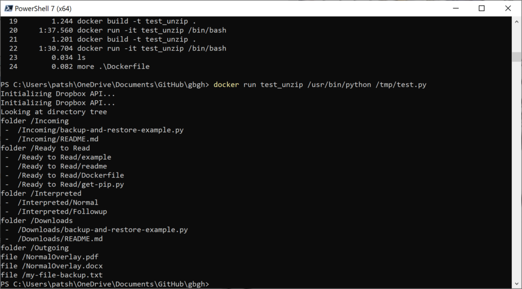
docker run test_unzip /usr/bin/python /tmp/test.py

to automate our python script. The beautiful part of this is that all of the complexity and logic is stored in the test.py file to automate the unzip part and the user just needs to open a command line and execute the docker run command to unzip the files. Secondary commands can be run with a different python script or java script and we should not need to change the base docker image to change functionality. Once the execution is complete, the docker image terminates and minimizes our cost in the cloud or performance impact on our desktop.

The test.py file is relatively simple. The two key elements in the python file are the connection to dropbox with the connection using a user generated token to access a folder. Once the token is generated for access from the http://dropbox.com/developer website it can be incorporated into the code

dbx = dropbox.Dropbox(“<token>”)

or passed in from the command line to make the code a little more secure. Once we have the dropbox connection we can navigate the folder entries by getting a folder list and testing to see if the file name is a folder or an actual file.

result = dbx.files_list_folder(path=””)
for entry in result.entries:
if isinstance(entry, dropbox.files.FileMetadata):
print(“file”,entry.path_display)
else:
print(“folder”,entry.path_display)
result2 = dbx.files_list_folder(entry.path_display)
for entry2 in result2.entries:
print(” – “,entry2.path_display)

This code uses the file_list_folder to get the current contents of the root directory. If the entry is a dropbox.files.FileMetadata then the file is an actual file. If it is not a file we assume that it is a folder and drop down one more level to look at the file entries that are one level deeper. If we execute this code with the docker run command we get the following output.

Automating the unzip process should be a simple case of finding a zip file in the Incoming folder, downloading it to the Ubuntu instance, unzipping it into a folder and uploading the contents of that folder into the Ready to Read folder on Dropbox. The eventual goal is to generate a Docker image, push it to an Azure Container Repository and trigger launching the run command when a file is uploaded to a storage container rather than Dropbox. We still want to push the unzipped files to Dropbox since this is the way that the doctors get the data to interpret. Once we have this done we can work on automating the stamping and communicating results part into a second python script based on the same Docker / Azure Container image.

Microsoft AZ-104 – Azure Admin Certification/Resources, Networks, and Terraform

In my last two blog posts covering Groups and Roles, the recommendation was to not use Terraform to initialize either of these features of Azure. If we step back and look at what Terraform is good at and what Azure is good at we recognize that the two don’t overlap. Terraform is good at creating infrastructure from a definition. If you have a project that you need to build, Terraform is very good at wrapping everything into a neat package and provides the constructs to create, update, and destroy everything. They key work here is everything. If you have something that builds foundation above the project level and provides the foundation for multiple projects destruction of these constructs has reach beyond just a single project. Azure is also very good at creating a boundary around projects as we will see with Resource Groups but also has tools to build resources above the project layer that cross multiple projects. Roles and Groups are two examples of this higher layer. You might create a database administrator group or a secure network connection back to your on-premises datacenter that helps with reliability and security of all projects. Unfortunately, defining these terms in a Terraform project could potentially ruin other projects that rely upon a user or group or role existing. Rather than defining a resource to create users, groups, or roles it was suggested that a local-exec script be called to first test if the necessary definitions exist then create them if needed. The script would then avoid deletion during the destroy phase and not re-create the resource or error out if the resource did not exist. An exec script would allow for conditional testing and creating of these elements on the first execution and only on the first execution. Consider the case where you have a development workspace and a production workspace. There is no need to create a new role or a new group in Azure specific to that workspace. There is a need to create a new resource group and network definition but not a new set of users, groups and roles.

Diagram that shows the relationship of management hierarchy levels

Using the diagram from the Microsoft documentation, creation of a tenant (Management group) or subscription does not make sense. Creating of a Resource group and Resources in Terraform is where the two fit perfectly. Consider the example of a three tiered architecture with virtual machines and web apps running in one resource group and a database running in another resource group. An alternate way of creating this is to create multiple subnets or virtual private networks and put everything in one resource group.

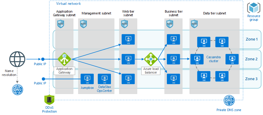
Note that we have one resource group, one virtual private network, a web tier on one subnet and a business and data tier on their own subnets. These deployments can cross multiple zones and all get wrapped with firewalls, network security rules, and DDoS protection. A simpler network configuration using SQL Server might look like the following diagram.

We create one resource group, one virtual network, five subnets in the same vnet, five network security groups, and three public IP addresses. Each subnet will contain an availability set that can scale with multiple virtual machines and have a load balancer where appropriate to communicate outside the subnet to other subnets or the public internet.

An Azure Resource Group can easily be reference using the azurerm_resource_group data declaration or the azurerm_resource_group resource declaration. For the data declaration the only required field is the resource group name. For the resource declaration we also have to define the location or Azure region where the resource group will be located. You can define multiple resource groups in different regions as well as define multiple azurerm providers to associate billing with different cost centers. In the simple example above we might want to associate the Active Directory and Bastion (or Jump box) servers with the IT department and the rest of the infrastructure with the marketing or engineering departments. If this project were a new marketing initiative the management subnet and AD DS subnet might be data declarations because they are used across other projects. All other infrastructure components will be defined in a Terraform directory and created and destroyed as needed.

To declare a virtual network we can use the azurerm_virtual_network data declaration or azurerm_virtual_network resource declaration. The data declaration requires a name and resource group while the resource declaration needs an address space and region definition as well. Under the virtual network we can declare a subnet with the azurerm_subnet data declaration or azurerm_subnet resource declaration. The data declaration requires a name, resource group, and virtual network while the resource declaration also needs either an address prefix or prefixes to define the subnet. Once we have a subnet defined we can define an azurerm_network_security_group resource or data declaration and associate it with a subnet using the azurerm_subnet_network_group_association resource to map the security to our subnet. All of these declarations are relatively simple and help define and build a security layer around our application.

In a previous blog post we talked about how to perform networking with AWS. The constructs for Azure are similar but have a resource group layered on top of the networking component. For AWS we defined a aws provider then an aws_vpc to define our virtual network. Under this network we created an aws_subnet to define subnets. For AWS we defined an aws_security_group and associated it with our virtual network or vpc_id.

Azure works a little differently in that the azurerm_network_security_group is associated with an azurerm_subnet and not the azurerm_virtual_network.

provider "azurerm" {
    features {}
}

resource "azurerm_resource_group" "example" {
  name     = "Simple_Example_Resource_Group"
  location = "westus"
}

resource "azurerm_virtual_network" "example" {
  name                = "virtualNetwork1"
  location            = azurerm_resource_group.example.location
  resource_group_name = azurerm_resource_group.example.name
  address_space       = ["10.0.0.0/16"]
}


resource "azurerm_subnet" "example" {
  name                 = "testsubnet"
  resource_group_name  = azurerm_resource_group.example.name
  virtual_network_name = azurerm_virtual_network.example.name
  address_prefixes     = ["10.0.1.0/24"]
}

resource "azurerm_network_security_group" "example" {
  name                = "acceptanceTestSecurityGroup1"
  location            = azurerm_resource_group.example.location
  resource_group_name = azurerm_resource_group.example.name

  security_rule {
    name                       = "test123"
    priority                   = 100
    direction                  = "Inbound"
    access                     = "Allow"
    protocol                   = "Tcp"
    source_port_range          = "*"
    destination_port_range     = "*"
    source_address_prefix      = "*"
    destination_address_prefix = "*"
  }
}

resource "azurerm_subnet_network_security_group_association" "example" {
  subnet_id                 = azurerm_subnet.example.id
  network_security_group_id = azurerm_network_security_group.example.id
}

Overall, this is a relatively simple example. We could declare four more subnets, four more network security groups, and four more network security group associations. Each network security group would have different definitions and allow traffic from restricted subnets rather than a wildcard allowing all access from all servers and ports. Terraform is very clean when it comes to creating a nice and neat resource group package and cleaning up with the destroy command all of the resources and network definitions defined under the resource group. This sample main.tf file is shared on github and only requires that you run the following commands to execute

  • open a PowerShell with the az cli enabled
  • download the main.tf file from github
  • az login
  • terraform init
  • terraform plan
  • terraform apply
  • terraform destroy

The plan and destroy are optional parameters. All of this can be done from cloud shell because Microsoft has preconfigure Terraform in the default cloud shell environment. All you need to do is upload the main.tf file to your cloud shell environment our mount a shared cloud storage and execute the init and apply commands.

Microsoft AZ-104 – Azure Admin Certification/Roles and Terraform

In a previous blog we talked about Azure AD and Tenant, Subscription, and User administration as well as Azure AD Group management and Terraform and how to map these functions to Terraform. In this blog we will continue this discussion but move onto Roles and RBAC in Azure.

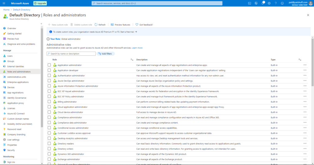
Roles and administrators in Azure Active Directory help define actions that can be performed by users, groups, and services. Some roles, for example, are account specific allowing users or members of groups to create other users and groups or manage billing. Other roles allow not only users and groups to manage virtual machines but also allows services and other virtual machines to manage virtual machines. Backup software, for example, needs to be able to update or create virtual machines. The backup software can be associated with a service and that service needs to have permission to be able to read, update, and create new virtual machines.

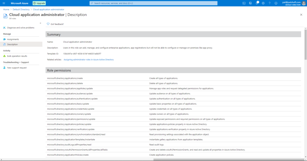
If we select one of the pre-defined roles we can look at the Role permissions. Selecting the Cloud application administrator shows a list of Role permissions associated with this Role definition.

Looking at the Microsoft documentation on Azure Roles, there are four general build-in roles

  • contributor – full access to resource but can not pass role to other users, groups, or services
  • owner – full access to resources
  • reader – view only role but can not make changes to anything
  • user access administrator – can change user access to resource but can’t do anything with the resource like read, update, delete, or create.

Associated with these base roles are pre-defined roles to allow you to perform specific functions. These roles have actions associated with the role and the actions can either allow or prohibit an action. An example of this would be the pre-defined role of “Reader and Data Access”. This role allows for three actions, Microsoft.Storage/storageAccounts/listKeys/action, Microsoft.Storage/storageAccounts/ListAccountSas/action, and Microsoft.Storage/storageAccounts/read. Note none of these permissions allow for create, delete, or write access. This user can read and only read data associated with a Storage Account.

If we look at role related functions in the azuread provider in Terraform, the only role related call is the azureread_application_app_role resource declaration. This resource declaration applies to application_objects and not users. This is not the roles that we are talking about in the previous section.

If we look at the role related functions in the azurerm provider in Terraform, we get the ability to define a role with the azurerm_role_definition data source as well as the azurerm_role_definition and azurerm_role_assignement resource definition. The role assignment allows us to assign roles to a user or a group. The role definition allows us to create custom roles which allows us to associate a role name to actions and disabled actions through a permission block. The scope of the role definition can be associated with a subscription, a resource group, or a specific resource like a virtual machine. The permissions block allows for the definition of actions, data actions, not_actions, and not_data_actions. A permission must include a wildcard [*] or a specific Azure RM resource provider operation as defined by Microsoft. These operations map directly to actions that can be performed in Azure and are very unique to Azure and Microsoft operations in Azure. This list can also be generated from the Get-AzProviderOperations or az provider operations list commands in PowerShell and the Azure CLI.

All of these operations can be performed with the Get-AzRoleDefinition, New-AzRoleDefinitions, Remove-AzRoleDefinition, Set-AzRoleDefinition, Get-AzRoleAssignment, New-AzRoleAssignment, Set-AzRoleAssignment, and Remove-AzRoleAssignment commands in PowerShell. My recommendation is to use the local-exec command to call these command line functions rather than coding them in Terraform. Scripts can be generated to create, update, and delete roles as needed to run outside of Terraform or as a local-exec call. Given that roles typically don’t get updated more than once or twice during a project automating the creation and destruction of a role can cause unnecessary API calls and potential issues if projects overlap with role definitions. One of the drawbacks to Terraform is that it does not have the cross project ability to recognize that a resource like a role definition is used across multiple workspaces or projects. Terraform treats the resource declaration as something absolute to this project and creates and destroys resources on subsequent runs. The destruction of a role can adversely effect other projects thus the creation and destruction should be done either at a higher level and reference it with a data declaration rather a resource declaration or provisioned through scripts run outside of Terraform.

In summary, roles are an important part of keeping Azure safe and secure. Limiting what a user or a service can do is critical in keeping unwanted actions or services from corrupting or disabling needed services. Role definitions typically span projects and Terraform configurations and are more of an environment rather than a resource that needs regularly refreshed. Doing role creation and assignments in Terraform can be done but should be done with care because it modifies the underlying environment that crosses resource group boundaries and could potentially negatively impact other projects from other groups.

Microsoft AZ-104 – Azure Admin Certification/Groups and Terraform

In a previous blog we talked about Azure AD and Tenant, Subscription, and User administration and how to map these functions to Terraform. In this blog we will continue this discussion but move onto Groups, IAM, and RBAC in Azure.

Groups are not only a good way to aggregate users but associate roles with users. Groups are the best way to associate roles and authorizations to users rather than associate them directly to a user. Dynamic groups are an extension of this but only available for Premium Azure AD and not the free layer.

Group types are Security and Microsoft 365. Security groups are typically associated with resource and role mappings to give users indirect association and responsibilities. The Microsoft 365 group provides mailbox, calendar, file sharing, and other Office 365 features to a user. This typically requires additional spend to get access to these resources while joining a security group typically does not cost anything.

Membership types are another group association that allows users to be an assigned member, a dynamic member, or a device to be a dynamic device. An example of a dynamic user would look at an attribute associated with a user and add them to a group. If, for example, someone lives in Europe they might be added to a GDPR group to host their data in a specific way that makes then GDPR compliant.

Role based access control or RBAC assign roles to a user or group to give them rights to perform specific functions. Some main roles in Azure are Global Administrator, User Administrator, or Billing Administrator. Traditional Azure roles include Owner, Contributor, Reader, or Administrator. Custom roles like backup admin or virtual machine admin can be added or created as desired to allow users to perform specific functions or job duties. Processes or virtual machines can be assigned RBAC responsibilities as well.

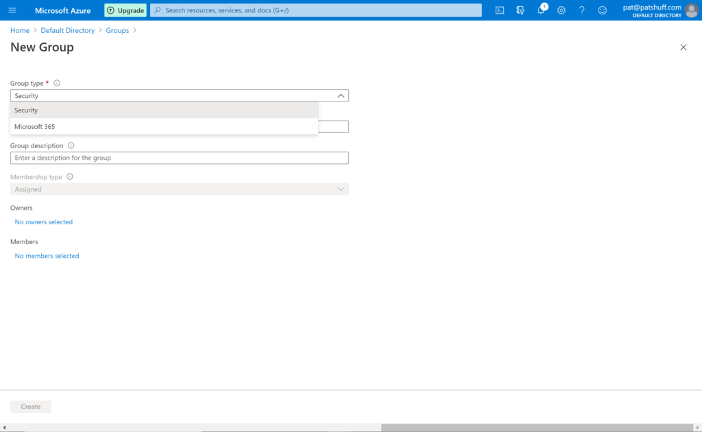
Groups are a relatively simple concept. You can create a Security or Microsoft 365 Group. The membership type can be Assigned, Dynamic, or Dynamic Device if those options are enabled. For corporate accounts they are typically enabled but for evaluation or personal accounts they are typically disabled.

Note that you have two group types but the Membership type is grey and defaults to Assigned. If you do a search in the azuread provider you can reference an azuread_group with data sources or create and manage an azuread_group with resources. For a data source azuread_group either name or object_id must be specified. For a resource azuread_group a name attribute is required but description and members are not mandatory. It is important to note that the group definition default to security group and there is no way to define a Microsoft 365 group through Terraform unless you load a custom personal provider select this option.

If you a search for group in the azurerm provider you get a variety of group definitions but most of these refer to the resource group and not groups associated with identity and authentication/authorization. Alternatively, groups can refer to storage groupings or sql groups for sql clusters. There are no group definitions like there were user definitions in the azurerm provider.

provider "azuread" {
}

resource "azuread_group" "simple_example" {
  name   = "Simple Example Group"
}

resource "azuread_user" "example" {
  display_name          = "J Doe"
  password              = "notSecure123"
  user_principal_name   = "jdoe@hashicorp.com"
}

resource "azuread_group" "example" {
  name    = "MyGroup"
  members = [
    azuread_user.example.object_id,
    /* more users */
  ]
}

data "azuread_group" "existing_example" {
  name = "Existing-Group"
}


resource "azuread_group_member" "example" {
  group_object_id   = azuread_group.example.id
  member_object_id  = data.azuread_user.example.id
}

In summary, group management from Terraform handles the standard use case for user and group management. Users can be created as a standard Azure AD user and associated with a Security group using the azuread_group_member resource. Existing groups can be declared with the data declaration or created with the resource declaration. Group members can be associated and deleted using Terraform. Not all the group functionality that exists in Azure is replicated in Terraform but for the typical use case all functionality exists. Best practice would suggest to do group associations and user definitions outside of Terraform using scripting. Terraform can call these scripts using local-exec commands rather than trying to make everything work inside of Terraform declarations.

Microsoft AZ-104 – Azure Admin Certification/Identity and Terraform

I am currently going through the A Cloud Guru AZ-104 Microsoft Azure Administrator Certification Prep class and thought I would take the discussion points and convert them into Terraform code rather than going through the labs with Azure Portal or Azure CLI.

Chapter 3 of the prep class covers Identity. The whole concept behind identity in Azure centers around Azure AD and Identity Access Management. The breakdown of the lectures in the acloud.guru class are as follows

  • Managing Azure AD
  • Creating Azure AD Users
  • Managing Users and Groups
  • Creating a Group and Adding Members
  • Configuring Azure AD Joing
  • Configuring Multi-factor authentication and SSPR

Before we dive into code we need to define what Azure AD and IAM are. Azure AD is the cloud based identity and access management solution (IAM) for the Azure cloud. AzureAD handles authentication as well as authorization allowing users to log into the Azure Portal and perform actions based on group affiliation and authorization roles (RBAC) associated with the user or the group.

There are four levels of Azure AD provided by Microsoft and each has a license and cost associated with consumption of Azure AD. The base level comes with an Azure license and allows you to have 500,000 directory objects and provides Single Sign-On (SSO) with other Microsoft products. This base license also has integration with IAM and business to business collaboration for federation of identities. The Office 365 License provides an additional layer of IAM with Microsoft 365 components and removes the limit on the number of directory objects. The Premium P1 and Premium P2 license provide additional layers like Dynamic Groups and Conditional Access as well as Identity Protection and Identity Governance for the Premium P2. These additional functions are good for larger corporations but not needed for small to medium businesses.

Two terms that also need definition are a tenant and a subscription. A tenant represents an organization via a domain name and gets mapped to the base Azure Portal account when it is created. This account needs to have a global administrator associated with the account but more users and subscriptions associated with it. A subscription is a billing entity within Azure. You can have multiple subscriptions under a tenant. Think of a subscription as a department or division of your company and the tenant as your parent company. The marketing department can be associated with a subscription so that billing can be tied to this profit and loss center while the engineering department is associated with another subscription that allows it to play with more features and functions of Azure but might have a smaller spending budget. These mapping are doing by the global administrator by creating new subscriptions under a tenant and giving the users and groups associated with the subscription rights and limits on what can and can’t be done. The subscription becomes the container for all Azure resources like storage, network configurations, and virtual machines.

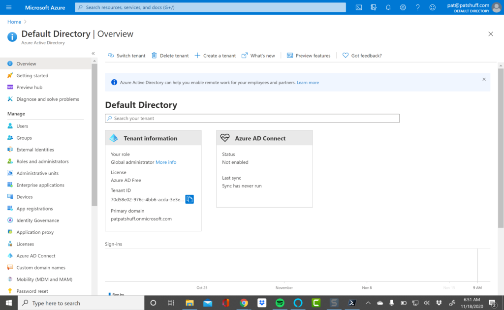
If we look at the Azure AD Terraform documentation provided by HashiCorp we notice that this is official code provided by HashiCorp and provides a variety of mechanisms to authenticate into Azure AD. The simplest way is to use the Azure CLI to authenticate and leverage the authentication tokens returned to the CLI for Terraform to communicate with Azure. When I first tried to connect using a PowerShell 7.0 shell and the Az module the connection failed. I had to reconfigure the Azure account to allow for client authentication from the PowerShell CLI. To do this I had to go to the Azure AD implementation in the Azure Portal

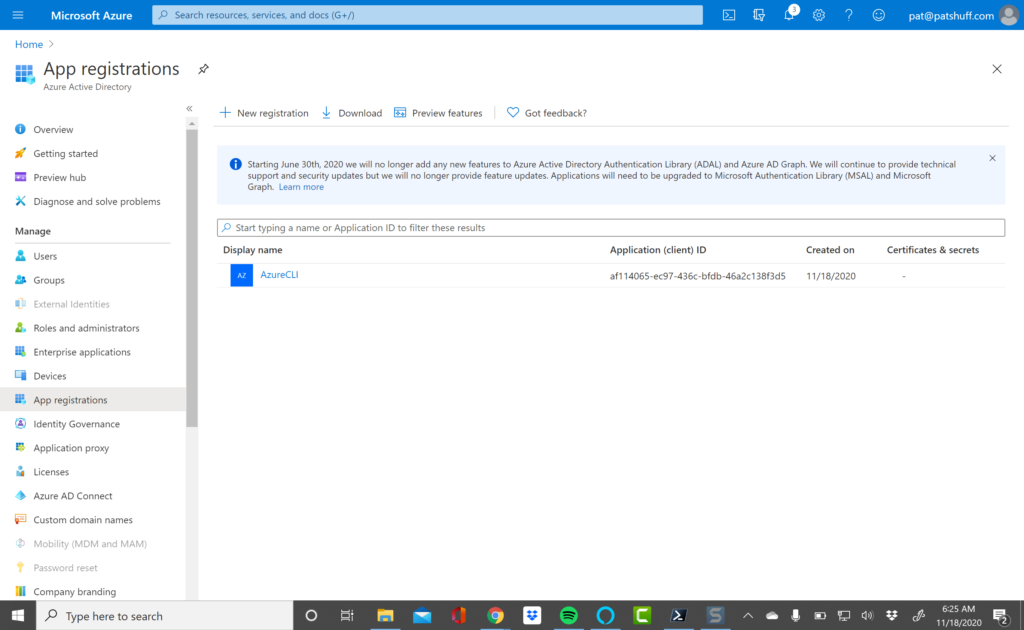
then create a new App registration (I titled it AzureCLI because the name does not matter)

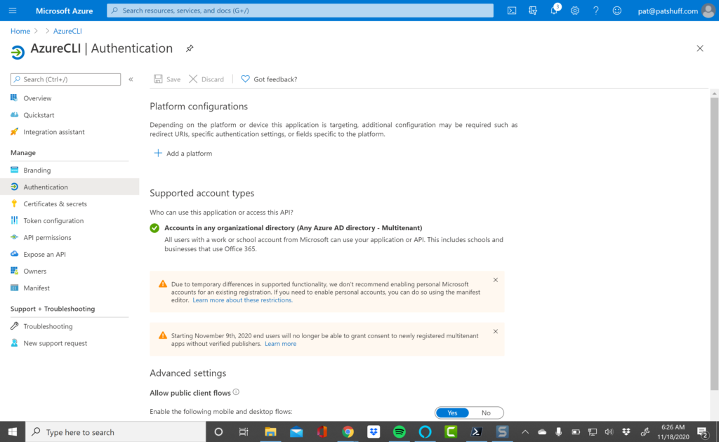
then changed the Allow public client flows from No to Yes to enable the Az CLI to connect.

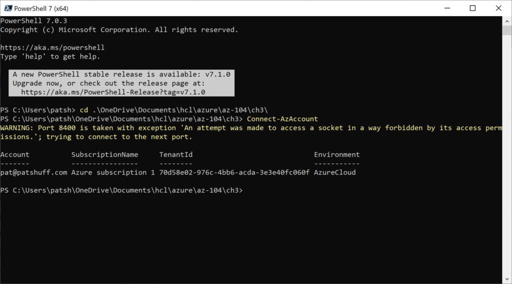
Once the change was made in the Azure Portal the Connect-AzAccount conneciton works with the desired account connection.

Note that there is one subscription associated with this account and only one is shown. The Terraform azuread provider does not provide a new way of creating a tenant because typically this is not used very often. You can create a new tenant from the Azure Portal and this basically creates a new Primary domain that allows for a new vanity connection for users. In this example the primary domain is patpatshuff.onmicrosoft.com because patshuff.onmicrosoft.com was taken by another user. We could create a new domain patrickshuff.onmicrosoft.com or shuff.onmicrosoft.com since neither have been taken. Given that the vanity domain name has little consequence other than email addresses, creating a new tenant is not something that we will typically want to do and not having a way of creating or referencing a tenant from Terraform is not that significant.

SiliconValve posted a good description of Tenants, Subscriptions, Regions, and Geographies in Azure that is worth reading to understand more about tenants and subscriptions.

The next level down from tenants is subscriptions. A subscription is a billing entity in Azure and resources that are created like compute and storage are associated with a subscription and not a tenant. A new subscription can be created from the Azure portal but not through Terraform. Both the subscription ID and tenant ID can be pulled easily from Azure using the azuread_client_config data element and the azuread provider. Neither of these are required to use the azurerm provider that is typically used to create storage, networks, and virtual machines.

One of the key reasons why you would use both the azuread and azurerm provider is that you can pass in subscription_id and tenant_id to the azurerm provider. These values can be obtained from the azuread provider. Multiple azuread connections can be made to azuread using the alias field as well as passing credentials into the connection rather then using the default credentials from the command line connection in the PowerShell or command console that is executing the terraform binary. Multiple subscriptions can also be managed for one tenant by passing in the subscription ID into the azurerm provider and using an alias for the azurerm definition. Multiple subscriptions can be returned using the azurerm_subscriptions data declaration this reducing the need to use or manage the azuread provider.

Now that we have tenants and subscriptions under our belt (and don’t really need to address them with Terraform when it comes to creating the elements) we can leverage the azurerm provider to reference tenant_id and subscription_id to manage users and groups.

Users and Groups

Azure AD users are identities of an Azure AD tenant. A user is ties to a tenant and can be an administrator, member user, or guest user. An administrator user can take on different roles like global administrator, user administrator, or service administrator. Member users are users associated with the tenant and can be assigned to groups. Guest users are typically used to share documents or resources without storing credentials in Azure AD.

To create a user in AzureAD the azuread provider needs to be referenced and the resource azuread_user or data source azuread_user needs to be referenced. For the datasource the user_principal_name is the only required field (username). Multiple users can be referenced with the azuread_users data source with a list of multiple user_principal_names, object_ids, or mail_nicknames required to identify users in the directory. For the resource definition a user_principal_name, display_name, and password are required to identify a user. Only one user can be define at a time and a block module declaration can be created to take a map entry into a block definition to reduce the amount of terraform code needed to define multiple users.

provider "azuread" {
  version = "=0.7.0"
}

resource "azuread_user" "example" {
  user_principal_name = "jdoe@hashicorp.com"
  display_name        = "J. Doe"
  password            = "SecretP@sswd99!"
}

The user is mapped to the default tenant_id and subscription_id that is used during the azuread provider creation. If you are using the az command line it is the default tenant and subscription associated with the login credentials used.

Bulk operations as is available from the Azure portal to use a csv file defining users is not available from terraform. This might be a good opportunity to create a local-exec provision definition to call the Azure CLI that can leverage bulk import operations as discussed in the https://activedirectorypro.com/create-bulk-users-active-directory/ blog entry. Given that bulk import is typically a one time operation automating this in Terraform is typically not needed but can be performed with a local-exec if desired.

A sample Terraform file that will create a list of users is shown below:

provider "azuread" {
}

variable "pwd" {
  type = string
  default = "Password123"
}

variable "user_list" {
  type = map
  description = "list of users to create"
  default = {
    "0" = ["Bob@patpatshuff.onmicrosoft.com","Bob"],
    "1" = ["Ted@patpatshuff.onmicrosoft.com","Ted"],
    "2" = ["Alice@patpatshuff.onmicrosoft.com","Alice"]
  }
}

resource "azuread_user" "new_user" {
      user_principal_name = "bill@patpatshuff.onmicrosoft.com"
      display_name = "Bill"
      password = "Password_123"
}

resource "azuread_user" "new_users" {
  for_each = var.user_list
  user_principal_name = var.user_list[each.key][0]
  display_name = var.user_list[each.key][1]
  password = var.pwd
}

The definition is relatively simple. The user_list contains a list of usernames and display names and there are two examples of creating a user. The first is the new_user resource to create one user and the second is the new_users resource to create multiple users. Users just need to be added to the user_list and are created with the var.pwd (from the default or variable passed in via the command line or environment variable. The for_each walks through the user_list and creates all of these users. A terraform apply will create everything the first time and a terraform destroy will cleanup after you are finished.

In summary, tenants, subscriptions, and users can be managed from Terraform. Tenants and subscriptions are typically read only elements that can be read from a connection and not created or updated from Terraform. Users can be added, updated, or deleted easily using the azuread provider. Once we have the user created we can dive deeper into (in a later blog) role management, RBAC, and IAM definitions using azuread or azurerm providers.