Deploying an AWS instance from Marketplace images using Terraform

In a previous post we looked at network requirements required to deploy an instance in AWS. In this post we are going to look at what it takes to pull a Marketplace Amazon Machine Instance (AMI) from the marketplace and deploy it into a virtual private cloud with the appropriate network security group and subnet definitions.

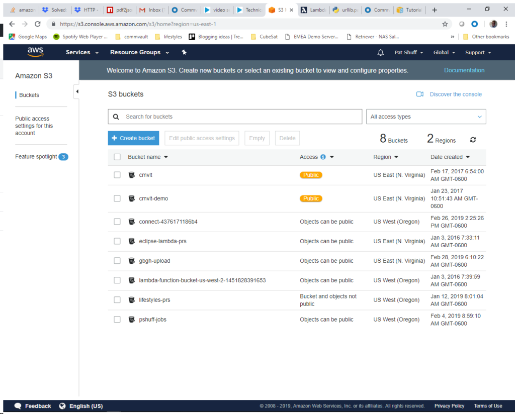
If you go into the AWS Marketplace from the AWS Console you get a list of virtual machine images. We are going to deploy a Commvault CommServe server instance because it is relatively complex with networking requirements, SQL Server, IIS Server, and customization after the image is deployed. We could just as easily have done a Windows 2016 Server or Ubuntu 18 Server instance but wanted to do something a little more complex.

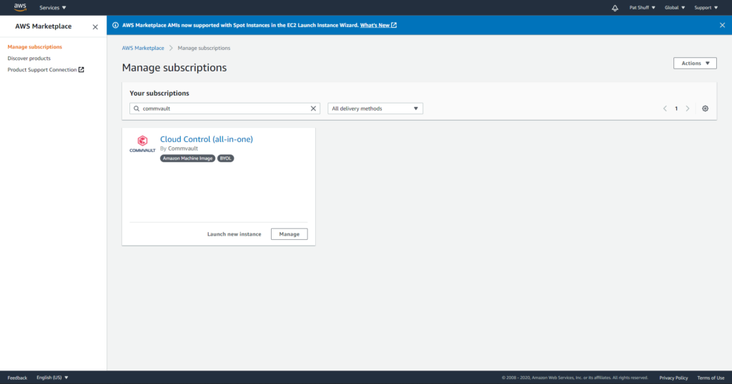
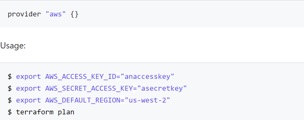
The Cloud Control is a Windows CommServe server installation. The first step needed is to open a PowerShell and connect to Amazon using the aws command line interface. This might require an Install-Module aws to get the aws command line installed and configured but once it is ready to connect to aws by typing in

aws configure

We can search for Marketplace images by doing an ec2 describe-images with a filter option

aws ec2 describe-images –executable-users all –filters “Name=name,Values=*Cloud Control*”

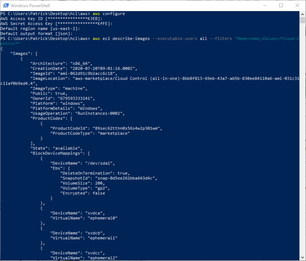
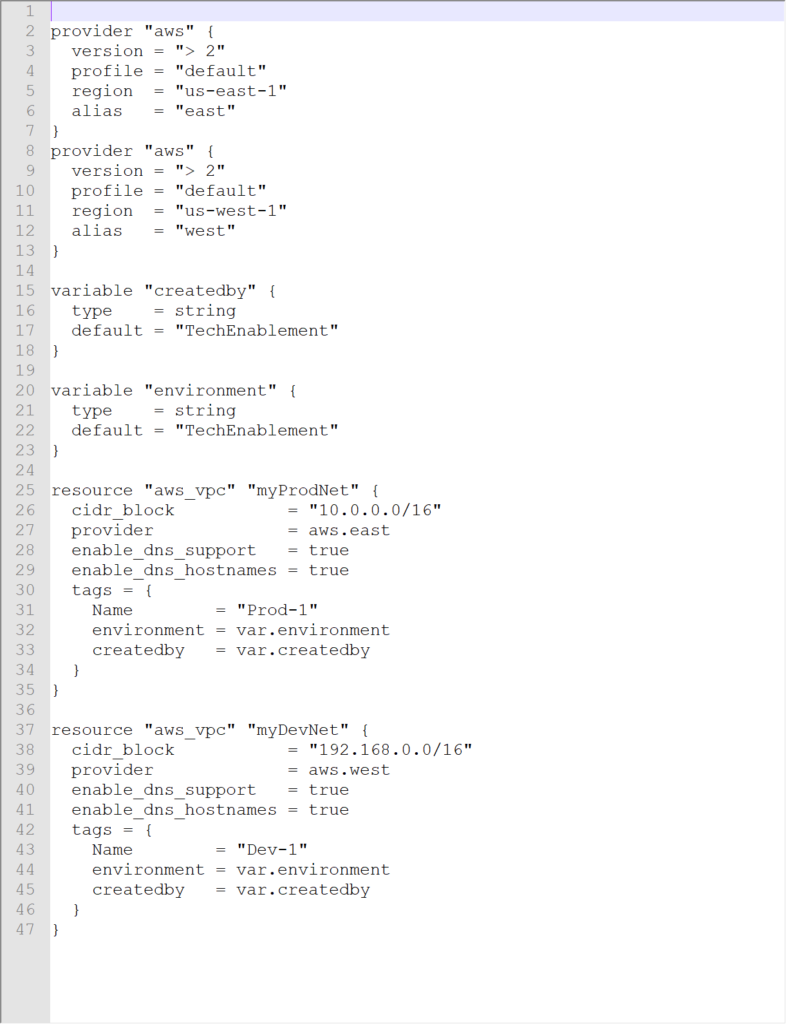
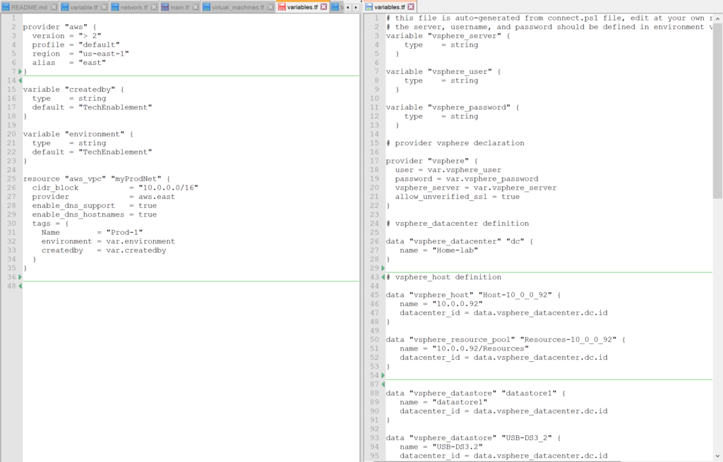
The describe-images command searches for an Amazon AMI that matches the description that we are looking for and returns an AMI ID. From this we can create a new instance pre-configured with a CommServe server. From here we can create out terraform files. It is important to note that the previous examples of main.tf and network.tf files do not need to be changed for this definition. We only need to create a virtual_machine.tf file to define our instance and have it created with the network configurations that we have previously defined.

We will need to create a new variable in our main.tf file that defines the private and public key that we are going to use to authenticate against our Windows server.

resource “aws_key_pair” “cmvlt2020” {
provider = aws.east
key_name = “cmvlt2020”
public_key = “AAAAB3NzaC1yc2EAAAADAQABAAABAQCtVZ7lZfbH8ZKC72A+ipNB6L/upQrj8pRxLwzQi7LVPrameil8/q4ROvWbC1KC9A3Ego”
}

A second element that needs to be defined is an aws_ami data declaration to reference an existing AMI. This can be done in the virtual_machines.tf file to isolate the variable and data declaration for virtual machine specific definitions. If we wanted to define an Ubuntu instance we would need to define the owner as well as the filter to use for an aws_ami search. In this example we are going to look for Ubuntu on an AMD 64-bit processor. The unusualness is the owners that needs to be used for Ubuntu since it is controlled by a third part Marketplace owner.

variable “ubuntu-version” {
type = string
default = “bionic”
# default = “xenial”
# default = “groovy”
# default = “focal”
# default = “trusty”
}

data “aws_ami” “ubuntu” {
provider = aws.east
most_recent = true
# owners = [“Canonical”]
owners = [“099720109477”]
filter {
name = “name”
values = [“ubuntu/images/hvm-ssd/ubuntu-${var.ubuntu-version}–amd64-server-“]
}
}

output “Ubuntu_image_name” {
value = “${data.aws_ami.ubuntu.name}”
}

output “Ubuntu_image_id” {
value = “${data.aws_ami.ubuntu.id}”
}

In this example we will be pulling the ubuntu-bionic-amd64-server image that has hardware virtualization running on a solid state disk. The variable ubuntu-version is mapped to the version of the Ubuntu kernel that is desired. The filter.values does the search in the Marketplace store to find the AMI ID. We restrict the search by searching in the region that we are deploying and use owner “099720109477” as the Marketplace provider.

If we compare this to a CentOS deployment the centos-version variable has a different string definition and a different owner.

variable “centos-version” {
type = string
default = “Linux 7 x86_64”
# default = “Linux 6 x86_64”
}

data “aws_ami” “centos” {
provider = aws.east
most_recent = true
owners = [“aws-marketplace”]

filter {
name = “name”
values = [“CentOS ${var.centos-version}*”]
}
}

output “CentOS_image_name” {
value = “${data.aws_ami.centos.name}”
}

output “CentOS_image_id” {
value = “${data.aws_ami.centos.id}”
}

For CentOS we can deploy 6 or version 7 by changing the centos-version.default definition. It is important to note that the owner of this AMI is not Amazon and uses the aws-marketplace definition to perform the filter. The same is true for the Commvault image that we are looking at.

data “aws_ami” “commvault” {
provider = aws.east
most_recent = true
# owners = [“Canonical”]
owners = [“aws-marketplace”]

filter {
name = “name”
values = [“*Cloud Control*”]
}
}

output “Commvault_CommServe_image_name” {
value = “${data.aws_ami.commvault.name}”
}

output “Commvault_CommServe_image_id” {
value = “${data.aws_ami.amazon.id}”
}

Note the filter uses a leading wildcard with the name “Cloud Control” followed by a wildcard to look for the instance that we are looking for. Once we have the AMI we can use the AMI.id from our search to define the aws_instance definition.

resource “aws_instance” “commserve” {
provider = aws.east
ami = data.aws_ami.commvault.id
associate_public_ip_address = true
instance_type = “m5.xlarge”
key_name = “cmvlt2020”
vpc_security_group_ids = [aws_security_group.cmvltRules.id]
subnet_id = aws_subnet.mySubnet.id
tags = {
Name = “TechEnablement test”
environment = var.environment
createdby = var.createdby
}
}

output “test_instance” {
value = aws_instance.commserve.public_ip
}

If we take the aws_instance declaration piece by piece the provider defines which AWS region that we will provision into Amazon. The vpc_security_group_ids and subnet_id defines what network that this instance will join. The new declarations are

  • ami – AWS AMI id to use as the source to clone
  • associate_public_ip_address – do we want a public or private only IP address with this instance
  • instance_type – this is the size. We need to reference the documentation or our users to figure out how large or how small this server needs to be. From the Commvault documentation the smallest recommended size is an m5.xlarge.
  • key_name – this is the public and private key names that will be used to connect to the Windows instance.

The remainder of the variables like disk, is this a Windows instance, and all the regular required parameters we saw with a vsphere_virtual_machine are provided by the AMI definition.

With these files we can execute from the following files

  • aws configure
  • terraform init
  • terraform plan
  • terraform apply

In summary, pulling an AMI ID from the marketplace works well and allows us to dynamically create virtual machines from current or previous builds. The terraform apply finishes quickly but the actual spin up of the Windows instance takes a little longer. Using Marketplace instances like the Commvault AMI provides a good foundation for a proof of concept or demo platform. The files used in this example are available in github.com.

aws provider vs vsphere provider

In a previous post we talked about the vsphere provider and what is needed to define a connection to create a virtual machine. In this blog we will start to look at what is needed to setup a similar environment to do the same thing in AWS EC2. Think of it as a design challenge. Your client comes to you and says “I want a LAMP or WAMP stack or Tomcat Server that I can play with. I want one local as well as one in the cloud. Can you make that happen?”. You look around and find out that they do have a vSphere server and figure out how to log into it and create a Linux instance to build a LAMP stack and a Windows instance to create a WAMP stack then want to repeat this same configuration in AWS, Azure, and/or Google GCP. Simple, right?

If you remember, to create a vSphere provider declaration in Terraform you basically need a username, password, and IP address of the vSphere server.

provider “vsphere” {
user = var.vsphere_user
password = var.vsphere_password
vsphere_server = var.vsphere_server
version = “1.12.0”

allow_unverified_ssl = true
}

The allow_unverified_ssl is to get around that most vSphere installations in a lab don’t have a certified certificate but a self-signed certificate and the version is to help us keep control of syntax changes in our IaC definitions that will soon follow.

The assumptions that you are making when connecting to a vSphere server when you create a virtual machine are

  1. Networking is setup for you. You can connect to a pre-defined network interface from vSphere but you really can’t change your network configuration beyond what is defined in your vSphere instance.
  2. Firewalls, subnets, and routing is all defined by a network administrator and you really don’t have control over the configuration inside Terraform unless you manage your switches and routers from Terraform as well. The network is what it is and you can’t really change it. To change routing rules and blocked or open ports on a network typically requires reconfiguration of a switch or network device.
  3. Disks, memory, and CPUs are limited by server configurations. In my home lab, for example, I have two 24 core servers with 48 GB of RAM on one system and 72 GB of RAM on the other. One system has just under 4 TB of disk while the other has just over 600 GB of disk available.
  4. Your CPU selection is limited to what is in your lab or datacenter. You might have more than just an x86 processer here and there but the assumption is that everything is x86 based and not Sparc or PowerPC. There might be an ARM processor as an option but not many datacenters have access to this unless they are developing for single board computers or robotics projects. There might be more advanced processors like a GPU or Nvidia graphics accelerated processor but again, these are rare in most small to midsize datacenters.

Declaring a vsphere provider gives you access to all of these assumptions. If you declare an aws or azure provider these assumptions are not true anymore. You have to define your network. You can define your subnet and firewall configurations. You have access to almost unlimited CPU, memory, and disk combinations. You have access to more than just an x86 processor and you have access to multiple datacenters that span the globe rather than just a single cluster of computers that are inside your datacenter.

The key difference between declaring a vsphere provider and an aws provider is that you can declare multiple aws providers and use multiple credentials as well as different regions.

provider “aws” {
version = “> 2”
profile = “default”
region = “us-east-1”
alias = “aws”
}

Note we don’t connect to a server. We don’t have a username or password. We do define a version and have three different parameters that we pass in. So the big question becomes how do we connect and authenticate? Where is this done if not in the provider connection? We could have gotten by with just provider “aws” {} and that would have worked as well.

To authenticate using the Hashicorp aws provider declaration you need to

  • declare the access_key and secret_key in the declaration (not advised)
  • declare the AWS_ACCESS_KEY_ID and AWS_SECRET_ACCESS_KEY_ID as environment variables
  • or point to a configuration file with the shared_credentials_file declaration or AWS_SHARED_CREDENTIALS_FILE environment variable leveraging the profile declaration or PROFILE environment variable.
  • automatic loading of the ~/.aws/credentials or ~/.aws/config files

The drawback to using the environment variables is that you can only have one login into your aws console but can connect to multiple regions with the same credentials. If you have multiple accounts you need to declare the access_key and secret_key or the more preferred method of using the shared_credentials_file declaration.

For the aws provider, all parameters are optional. The provider is flexible enough to make some assumptions and connect to AWS based on environment variables and optional parameters defined. If something is defined with a parameter it is used over the environment variable. If you define both a key and a shared_credentials_file, Terraform will throw an error. If you have environment variables define and a ~/.aws/credentials file, the environment variables will be used first.

If we dive a little deeper into our vsphere variables.tf file we note that we need to run a script or manually generate the declarations for vsphere_datacenter, vsphere_host, and vsphere_resource_pool prior to defining a virtual machine. With the aws provider we only need to define the region to define all of these elements. Unfortunately, we also need to define the networking connections, subnet definitions, and potential firewall exceptions to be able to access our new virtual machine. It would be nice if we could take our simple vsphere virtual machine definition defined in our vsphere main.tf file and translate it directly into an aws_instance declaration. Unfortunately, there is very little that we can translate from one environment to the other.

The aws provider and aws_instance declaration does not allow us to clone an existing instance. We need to go outside of Terraform and create an AMI to use as a reference for aws_instance creation. We don’t pick a datacenter and resource_pool but select a region to run our instance. We don’t need to define a datastore to host the virtual machine disks but we do need to define the disk type and if it is a high speed (higher cost) or spinning disk (lower cost) to host the operating system or data.

We can’t really take our existing code and run it through a scrubber and spit out aws ready code unfortunately. We need to know how to find a LAMP, WAMP, and Tomcat AMI and reference it. We need to know the network configurations and configure connections to another server like a database or load balancer front end. We also need to know what region to deploy this into and if we can run these services using low cost options like spot instances or can shut off the running instance during times of the day to save money given that a cloud instance charges by the minute or hour and a vsphere instance is just consuming resources that you have already paid for.

One of the nice things about an aws provider declaration is that you can define multiple providers in the same file which generated an error for a vsphere provider. You can reference different regions using an alias. In the declaration shown above we would reference the provider with

provider = aws.aws

If we wanted to declare that the east was our production site and the west was our dev site we could use the declaration

provider “aws” {
version = “> 2”
profile = “default”
region = “us-east-1”
alias = “east”
}
provider “aws” {
version = “> 2”
profile = “default”
region = “us-west-1”
alias = “west”
}

If we add a declaration of a network component (aws_vpc) we can populate our state file and see that the changes were pushed to our aws account.

We get the .terraform tree populated for our Windows desktop environment as well as the terraform.tfstate created. Looking at our AWS VPC console we see that Prod-1 was created in US-East-1 (and we could verify that Dev-1 was created in US-West-1 if we wanted).

Note that the CIDR block was correctly defined as 10.0.0.0/16 as desired. If we run the terraform destroy command to clean up this vpc will be destroyed since it was created and is controlled by our terraform declaration.

Looking at our terraform state file we can see that we did create two VPC instances in AWS and the VPC ID should correspond to what we see in the AWS console.

In summary, using Terraform to provision and manage resources in Amazon AWS is somewhat easier and somewhat harder than provisioning resources in a vSphere environment. Unfortunately, you can’t take a variables.tf or main.tf declaration from vSphere and massage it to become a AWS definition. The code needs to be rewritten and created using different questions and parameters. You don’t need to get down to the SCSI target level with AWS but you do need to define the network connection and where and how the resource will be declared with a finer resolution. You can’t clone an existing machine inside of Terraform but you can do it leveraging private AMI declarations in AWS similar to the way that templates are created in vSphere. Overall an AWS managed state with Terraform is easy to start and allows you to create a similar environment to an on-premises environment as long as you understand the differences and cost implications between the two. Note that the aws provider declaration is much simpler and cleaner than the vsphere provider. Less is needed to define the foundation but more is needed as far as networking and how to create a virtual instance with AMIs rather than cloning.

The variables.tf and terraform.state files are available on github to review.

Supporting multiple providers

One of the key uses of Terraform is to deploy development and production systems. Terraform can be used to manage what is deployed, manage resources, and restrict resources available to an instance. In our last blog entry we looked at the vSphere provider and looked at some of they key parameters that are needed to deploy solutions into this virtual environment.

In a perfect world we should be able to develop definitions to deploy development systems to a small or older system, deploy production to a more expensive and powerful vSphere cluster, and a disaster recovery copy to make sure that we can failover to an alternate datacenter in times of emergency. We should then be able to take the data for this provider and move it to Amazon AWS or Microsoft Azure or Google GCP by just changing the provider. Unfortunately, this is not a perfect world and there are a ton of reasons that this won’t work.

If we look at the documentation for the AWS provider we note that we don’t need a username and password or IP address but rather need a public and private key to connect to an AWS serviced and these parameters can be provided by command line environment variables. We can also define multiple providers and give an alias for the multiple providers and deploy services into different accounts, regions, and zones based on the terraform provider definition.

A typical aws provider main.tf file looks like…

provider “aws” {
version = “> 2”
profile = “default”
region = var.dev_location
alias = “dev”
}

provider “aws” {
version = “> 2”
profile = “default”
region = “us-west-1”
alias = “prod”
}

allowing you to deploy resources into “aws.dev” or “aws.prod” with a variable.tf file containing nothing or

variable “createdby” {
type = string
default = “TechEnablement”
}

variable “environment” {
type = string
default = “TechEnablement”
}

variable “dev_location” {
type = string
default = “us-east-1”
}

With this variable.tf definition you need to define environment variables to define the AWS_ACCESS_KEY_ID and AWS_SECRET_ACCESS_KEY or define shared_credentials_file in a terraform configuration file to point to the location of a key file. On Windows this is typically “%USERPROFILE%\.aws\credentials”. The format of the credentials file looks like

[default]

aws_access_key_id=AWSSAMPLE7EXAMPLE

aws_secret_access_key=long/keywith/numbers4&letters

Unfortunately the vSphere provider does not allow for an alias tag and use of different account credentials and vsphere host address. Rather than defining multiple providers you need to define different directories and different variable.tf and main.tf files for each of the environments. In our earlier example we would have a dev, prod, and dr folder under our main folder. Each folder would have terraform configuration files to define what each environment would look like and resources available.

A typical multi-environment tree would look different from out initial single tree deployment with a dev, prod, and dr folder each containing the same main.tf files but different variable.tf definitions. Each folder would have their own terraform.tfstate file as well given that there are different environment variables and states on different servers.

If you try to define multiple vsphere providers in one file you get the error

Given the differences between the two provider types it begs the question of changing the aws provider to the same file format as the vsphere provider and have three different folders that deploy different environments to different servers. This would work but having everything in one file reduces complexity and potential errors by having multiple copies in multiple folders. Editing one does not guarantee changes to the other directories and there might be subtle differences between the different environments, like datastore names or locations as well as network definitions, that are unique to each environment.

In summary, there are multiple ways of solving the same problem. The ultimate solution is to write a generic provider that can deploy services into vSphere, Hyper-V, Nutanix, other on-premises virtual machine hosts, AWS, Azure, Google GCP, and other cloud virtual machine hosts. Given that there is no generic provider that works across all or even multiple environments you have to decide how to deploy multiple terraform configuration files to multiple target locations without doubling or tripling your work and code that needs support and maintenance. My recommendation is to go with different folders for different environments and have different variable.tf and main.tf files in each folder.

Automating processes

Recently I have been working on my AWS Architect certification. Rather than just grinding through the training material and practice exams I thought I should actually build something and journal my process. I have done this internally for Commvault but wanted to do an external blog as well so that if I left Commvault I would have a copy of my notes.

The first step in building something is documenting the project including the goals, objectives, and components that will be needed. Initially I interviewed the person that I am building this project for and drew everything on paper (I know, old school). From there I transcribed it into an AWS architecture diagram using LucidChart.

The goal of the project is to take a zip file that is an aggregation of ECGs performed on student athletes and upload it into S3. Once the zip file is uploaded it kicks off a process that unzips the files and copies them to another folder inside the bucket. From here these files are copies to Dropbox and a notification is sent to one or more email boxes or text messages. From this notification a Cardiologist interprets the results and responds to the email or text. Once the response is received the interpreted files are transferred from Dropbox back into S3 and sorted according to the school that was screened. Students that were marked as low risk are stamped with a low risk label. Students that were marked needing a follow up or high risk are placed into a different folder for manual processing and a notification is sent via email and/or text requesting for manual intervention.

The first step in the process is taking a zip file that was uploaded into S3 and processing it. Fortunately we have the ability to launch processes when a file is uploaded into S3 with the Lambda functions. A good place to start learning about this is https://docs.aws.amazon.com/lambda/latest/dg/with-s3-example.html where the tutorial talks about how to create a Lambda function and tie it to changes to a specific bucket. This also required creating an IAM role that allows a Lambda function to read and write an S3 bucket.

Step 1) Create IAM Role. This id done by going to the IAM console and selecting Roles at the left of the screen. We want to click on the Create role blue button near the middle of the screen.


We select the Lambda function and click Next:Permissions at the bottom of the screen.

To make things easy we select AmazonS3FullAccess. What we want is the ability to read and write objects in an S3 bucket. We need to type in S3 in the Filter policies then select the box next to AmazonS3FullAccess.

We skip the tags role and go to Review. Here we enter a Role name. We will call it gbgh-processing. Once we enter this information we click Create role at the bottom right of the screen.

At this point we have a role that allows our Lambda function to access S3 objects and manipulate them.

Step 2) The next step is to create a bucket that we will upload files into. This is done by going to the S3 console and creating a bucket. The bucket must be in the same zone that we create our Lambda function. In our example we will create a bucket called gbgh-test and put it in the US East region.

We click on the Create bucket blue button at the top left of the screen. The bucket name needs to be unique and we want the US East region. We don’t want to copy settings from other buckets and will configure the options on our own. We will be using gbgh-test as the bucket name.

We will go with the default options and clear all of the permissions as shown below. We want to open up public access for our bucket because a variety of people long term will be uploading files into the bucket. We can control access through other mechanisms at a later date.

From here we click Next and Create Bucket on the next screen.

We should see our bucket ready and available in the S3 bucket list.

Step 3) create a Lambda function that receives S3 object changes so that we can process the files and do something with it. To do this we go to the Lambda function console.

Notice that we have a few functions already defined. Some are Java. Some are Node.js. Some are Python. We will be creating a Python 2.7 binary so that we can use the boto3 library. This pre-defined library allows us to quickly and easily manipulate objects in a bucket and call other AWS services like email and queue services. To start we click on the orange Create function button at the top right of the screen.

We will Author from scratch our code since we have some simple code that we can work from. We will call the function gbgh-test and select Python 2.7 as the runtime. We will select the gbgh-processing role to give our function access to the S3 bucket that we created.

When we click on the Create function it drops us into the Designer tool for editing and testing our Lambda function. The first thing that we want to do is add an S3 trigger to link S3 objects to our function.

The trigger is found under the Designer – Add triggers list. Scroll down and click on S3. It will show that Configuration is required and we will need to scroll down to configure the trigger. From here we will select the bucket and Event type. We are looking for create events which indicates that someone uploaded a file for us to process. We select the gbgh-test bucket and stick with the All object create events.

After clicking on Add we nativate to the gbgh-test icon to see the Function code where we can edit the function and test code that we want. The default handler does not do what we want so we need to replace this code.

For our function we are going to start simple. We will handle a create event, pull the bucket name from the event handler, pull the file name that was uploaded, and print all of the items in the bucket for testing. The code starts with an import of the boto3 library. We create a handle into S3 with the boto3.resource(‘s3’) library call. The lambda_handler is launched when a file is created in our S3 bucket. From here we print some diagnostics that the handler was called then walk the object list in the bucket and print the object names. From here we return and terminate the Lambda function. Sample code for this can be found at lambda_function_s3_upload.js

The next step is to create a test event to simulate a file upload. We do this by clicking on the Select a test event pulldown and selecting Configure test events.

For the test event we need to simulate an ObjectCreated:Put call or an https PUT that causes a file to be uploaded to our S3 bucket. We need to define the arn for our bucket and bucket name as well as an object name (gbgh.zip) that we need to actually create in our gbgh-test bucket. We define the event name as gbghTest and paste in our simulated event call. The code for this can be found at testS3Put.json

The data at the bottom of the screen are just curly brackets to finish out the record definition. From here we click on Create (I had to scroll down to see it) to create our test function. At this point we can select gbghTest and click on the Test button at the top right of the screen. When we first tried this it failed with an error. We had to add two lines to import the json and urllib functions since we call them to process the keys or object names. Once we make these changes we see that the status came back Succeeded and we get an empty listing of gbgh-test if we scroll down in the Execution results screen.

We can upload our gbgh.zip file into our gbgh-test bucket and it should appear at the bottom of the Execution results screen.

To summarize, we have a Lambda function that gets launched when we upload a file into an S3 bucket. Currently the function just prints a directory of the bucket by listing all of the objects that it contains. We had to create an IAM policy so that our function can interact with S3. In the next blog post we will do some processing of this zip file and send some notifications once the zip file is processed.