Raspberry Pi install

This is the start of a tutorial to help build a simple platform for robotic control and simple display options. We will start with a Raspberry Pi 4 and Raspberry Pi 5 as the initial platform. In the future we will look at an Arduino board using the Elegoo.com super starter kit Uno R3 Project kit.

This kit contains a bunch of electronic projects as well as an Arduino UNO R3 microcontroller.

Raspberry Pi

The Raspberry Pi 5 is the latest release of a microprocessor board release from raspberrypi.com.

This processor board was released in October of 2023 and is now generally available with 4 GB or 8 GB of memory for between $60 and $100 depending upon where you purchase the memory options.

The Raspberry Pi 4 is a lower power system with similar memory configurations starting at $35 and was released in June 2019.

The main difference between the Raspberry Pi 4 and Raspberry Pi 5 are processing power, display options, and expansion options

Both require a memory card to help boot the operating system and either a WiFi connection, ethernet connection, or keyboard/mouse/HDMI monitor to configure and setup the system.

The first key difference that will be obvious between the two boards is how they get power. The Pi4 gets power from a USB-C power adapter that is limited to 15 Watts (5 Volt/3 Amp minimum). The Pi5 needs a different power supply adapter that can power upto 27 Watts of power (5 Volt/5 Amp maximum).

The microSD memory card is inserted into the back of the Raspberry Pi. This memory card contains the operating system and file system that controls the microcomputer.

The only limitation for the microSD card size is the filesystem size for Linux. The physical size is restricted by definition so the size that we are talking about is the storage capacity. As of this posting in 2014, a 2 TB microSD card is the largest available on the market. The ext4 filesystem on Linux is 256 TB so there is plenty of room for larger microSD cards when they are available.

To get the operating system on the memory card, another operating system like Windows 10 or MacOS are needed to copy the OS image from the internet to the memory card. A USB to memory card adapter is needed.

Not all USB to card adapters can handle a microSD card and might need an adapter to handle the larger card slot.

A good place to start for imaging the operating system is https://www.raspberrypi.com/documentation/computers/getting-started.html which details the parts and software needed for both the Raspberry Pi 4 and 5. The software for Windows can be found at https://www.raspberrypi.com/software/ and is relatively easy to install but does require admin rights to allow you to communicate with the USB port/memory card. The software is relatively simple to use and has three options for installation.

The first option is to select the device (Raspberry Pi 4 or Raspberry Pi 4 or older models) .

The second option is which flavor of the operating system to install. The initial recommendation would be to install a full desktop that allows for connection via keyboard/mouse/HDMI monitor or remote connection across the WiFi network or ethernet network. At some point you might want to install a “headless” system that can only be connected to through a network connection and is typically only a terminal connection and not a full desktop experience. This configuration requires a bit more knowledge of Linux command line options and how to manipulate/configure your system.

You can install a 64 bit or 32 bit operation. The recommendation is to install the 64-bit configuration initially until you find a need for the 32-bot configuration or an application that requires 32-bit only.

The final configuration option is to select the microSD card that gets mounted on the Windows operating system. The drive name and device type will typically be different than this screen shot.

The final option is to configure the WiFi adapter, user/password, and hostname as part of the installation. This is done by clicking on the Edit Settings which gives you access to the optional configuration screens.

In this example we configure the network, add a user, and define the hostname. You will typically need to modify each of these entries to fit your needs.

It is suggested that you configure SSH at this point by going to the services tab and enabling the SSH option.

The simplest recommendation is to use password authentication until you are more familiar with secure shell and using secure communications without a password.

Once all options are defined, write the operating system to the memory card and eject it from your computer.

The copy operation will take a few minutes and write then verify the operation.

Take the microSD card and insert it into the back of the Raspberry Pi. The slot is the same for the Raspberry Pi 4 and Raspberry Pi 5.

Attach the power supply, ethernet cable (if used), keyboard, mouse, and HDMI connector to the Raspberry Pi.

At this point you should see a desktop screen on your monitor/TV and have a successful operating system installation.

Dropbox and docker

I am doing some volunteer work this week trying to help a non-profit process some data that they get on a regular basis. The process is relatively simple but time consuming involving a three step process.

Step 1, record and package medical data into a zip file. This zip file is uploaded to a Dropbox folder for a doctor to interpret the data. Unfortunately the software package that the doctor uses does not deal with zip files and needs the file unpacked. Automating the unzip process when a zip file is dropped into an /Incoming folder and dropping it into a folder assigned to the doctor would be helpful. There are some issues based on the unzip happening on MacOS or Windows that creates issues for the interpretation software so moving this to a Ubuntu docker instance will hopefully solve the problem.

Step 2, a doctor interprets the data and the data is written into a couple of folders. Once the data is properly sorted it needs to be stamped with a watermark and necessary additional documents attached on subsequent pages if follow up tests are requested. The files are in pdf format so overlaying a watermark or stamp on a pdf file needs to be automated because it is very time consuming and a tedious manual process.

Step 3 is returning the results to the patient or facility that recorded the data. This is typically done with a secure link and secure email communication. The message is custom based on the results of the test or tests so it really can’t be automated but the sharing of test results can be automated.

To solve this problem packaging everything into a docker image and creating a custom python script or java script that is uploaded into the docker image allows us to control the distribution as well as code control.

To build a docker image we just need to create a Dockerfile that loads the latest Ubuntu image and overlays curl, unzip, python3, and python3-pip packages. Once we have the base image created we can upload a python file and either execute the script to download the zip file, unzip the contents into a folder and upload this folder back to dropbox. For the Dockerfile we can use

# Create latest ubuntu instance

FROM ubuntu:latest
#

# label to document

#
LABEL maintainer=”pat@patshuff.com”
LABEL version=”0.1″
LABEL description=”test of unzip file in Dropbox”
#

# update and install unzip and Dropbox CLI

#
RUN DEBIAN_FRONTEND=noninteractive
RUN apt update
RUN apt install -y tzdata
RUN apt install -y curl unzip gnupg software-properties-common openjdk-8-jre-headless python3 python3-pip vim
RUN cp /usr/bin/pip3 /usr/bin/pip
RUN cp /usr/bin/python3 /usr/bin/python
RUN pip install dropbox
COPY test.py /tmp/test.py

If we look at this file we load from ubuntu and run some apt commands. We start with the apt update to make sure we have the latest patch. From there we set the timezone data to prevent inputs being required for the software-properties-common package installation. The final installation pulls in a variety of packages which include the unzip and python3 binaries. Once we have everything configured we pull the latest dropbox API libraries for Python and upload our test.py file from our desktop to the /tmp directory. Our users will never see this complexity and can run a simple command line once everything has been build and packaged with docker. The result can be run on MacOS, Windows, or a PowerShell command line in the cloud.

Building this is relatively simple with a

docker build -t test_unzip .

With this command an image is created labeled test_unzip that we can run from any system with a docker binary (Windows, MacOS, Azure Container, etc). We can push this to a docker hub account so that it can easily be pulled to any machine or cloud instance that we have access to. We can run the binary with

docker run -it test_unzip /bin/bash

to get an interactive command line or

docker run test_unzip /usr/bin/python /tmp/test.py

to automate our python script. The beautiful part of this is that all of the complexity and logic is stored in the test.py file to automate the unzip part and the user just needs to open a command line and execute the docker run command to unzip the files. Secondary commands can be run with a different python script or java script and we should not need to change the base docker image to change functionality. Once the execution is complete, the docker image terminates and minimizes our cost in the cloud or performance impact on our desktop.

The test.py file is relatively simple. The two key elements in the python file are the connection to dropbox with the connection using a user generated token to access a folder. Once the token is generated for access from the http://dropbox.com/developer website it can be incorporated into the code

dbx = dropbox.Dropbox(“<token>”)

or passed in from the command line to make the code a little more secure. Once we have the dropbox connection we can navigate the folder entries by getting a folder list and testing to see if the file name is a folder or an actual file.

result = dbx.files_list_folder(path=””)
for entry in result.entries:
if isinstance(entry, dropbox.files.FileMetadata):
print(“file”,entry.path_display)
else:
print(“folder”,entry.path_display)
result2 = dbx.files_list_folder(entry.path_display)
for entry2 in result2.entries:
print(” – “,entry2.path_display)

This code uses the file_list_folder to get the current contents of the root directory. If the entry is a dropbox.files.FileMetadata then the file is an actual file. If it is not a file we assume that it is a folder and drop down one more level to look at the file entries that are one level deeper. If we execute this code with the docker run command we get the following output.

Automating the unzip process should be a simple case of finding a zip file in the Incoming folder, downloading it to the Ubuntu instance, unzipping it into a folder and uploading the contents of that folder into the Ready to Read folder on Dropbox. The eventual goal is to generate a Docker image, push it to an Azure Container Repository and trigger launching the run command when a file is uploaded to a storage container rather than Dropbox. We still want to push the unzipped files to Dropbox since this is the way that the doctors get the data to interpret. Once we have this done we can work on automating the stamping and communicating results part into a second python script based on the same Docker / Azure Container image.

Microsoft AZ-104 – Azure Admin Certification/Resources, Networks, and Terraform

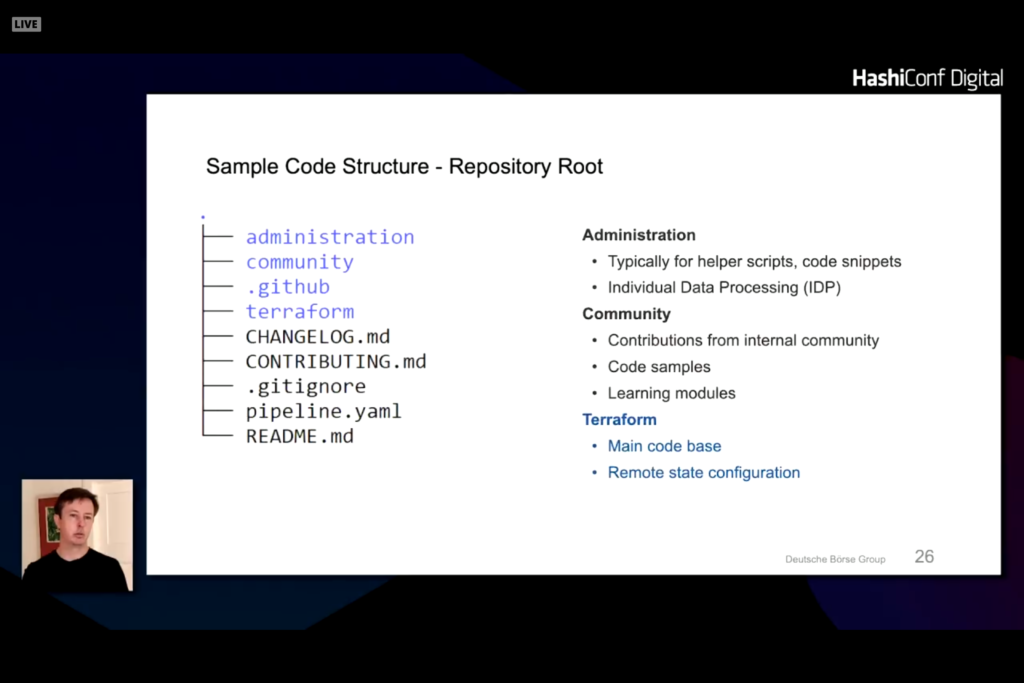
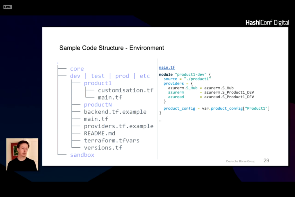
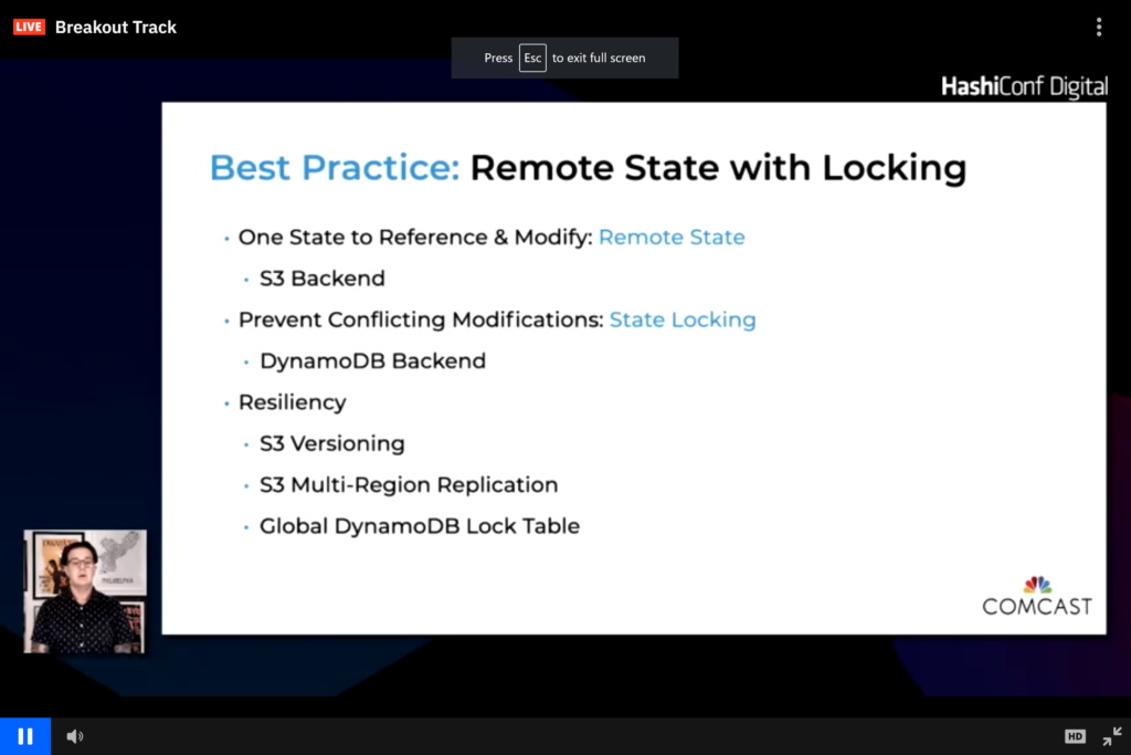
In my last two blog posts covering Groups and Roles, the recommendation was to not use Terraform to initialize either of these features of Azure. If we step back and look at what Terraform is good at and what Azure is good at we recognize that the two don’t overlap. Terraform is good at creating infrastructure from a definition. If you have a project that you need to build, Terraform is very good at wrapping everything into a neat package and provides the constructs to create, update, and destroy everything. They key work here is everything. If you have something that builds foundation above the project level and provides the foundation for multiple projects destruction of these constructs has reach beyond just a single project. Azure is also very good at creating a boundary around projects as we will see with Resource Groups but also has tools to build resources above the project layer that cross multiple projects. Roles and Groups are two examples of this higher layer. You might create a database administrator group or a secure network connection back to your on-premises datacenter that helps with reliability and security of all projects. Unfortunately, defining these terms in a Terraform project could potentially ruin other projects that rely upon a user or group or role existing. Rather than defining a resource to create users, groups, or roles it was suggested that a local-exec script be called to first test if the necessary definitions exist then create them if needed. The script would then avoid deletion during the destroy phase and not re-create the resource or error out if the resource did not exist. An exec script would allow for conditional testing and creating of these elements on the first execution and only on the first execution. Consider the case where you have a development workspace and a production workspace. There is no need to create a new role or a new group in Azure specific to that workspace. There is a need to create a new resource group and network definition but not a new set of users, groups and roles.

Diagram that shows the relationship of management hierarchy levels

Using the diagram from the Microsoft documentation, creation of a tenant (Management group) or subscription does not make sense. Creating of a Resource group and Resources in Terraform is where the two fit perfectly. Consider the example of a three tiered architecture with virtual machines and web apps running in one resource group and a database running in another resource group. An alternate way of creating this is to create multiple subnets or virtual private networks and put everything in one resource group.

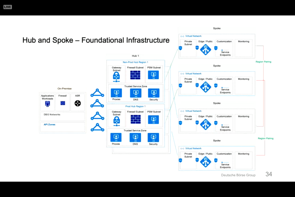
Note that we have one resource group, one virtual private network, a web tier on one subnet and a business and data tier on their own subnets. These deployments can cross multiple zones and all get wrapped with firewalls, network security rules, and DDoS protection. A simpler network configuration using SQL Server might look like the following diagram.

We create one resource group, one virtual network, five subnets in the same vnet, five network security groups, and three public IP addresses. Each subnet will contain an availability set that can scale with multiple virtual machines and have a load balancer where appropriate to communicate outside the subnet to other subnets or the public internet.

An Azure Resource Group can easily be reference using the azurerm_resource_group data declaration or the azurerm_resource_group resource declaration. For the data declaration the only required field is the resource group name. For the resource declaration we also have to define the location or Azure region where the resource group will be located. You can define multiple resource groups in different regions as well as define multiple azurerm providers to associate billing with different cost centers. In the simple example above we might want to associate the Active Directory and Bastion (or Jump box) servers with the IT department and the rest of the infrastructure with the marketing or engineering departments. If this project were a new marketing initiative the management subnet and AD DS subnet might be data declarations because they are used across other projects. All other infrastructure components will be defined in a Terraform directory and created and destroyed as needed.

To declare a virtual network we can use the azurerm_virtual_network data declaration or azurerm_virtual_network resource declaration. The data declaration requires a name and resource group while the resource declaration needs an address space and region definition as well. Under the virtual network we can declare a subnet with the azurerm_subnet data declaration or azurerm_subnet resource declaration. The data declaration requires a name, resource group, and virtual network while the resource declaration also needs either an address prefix or prefixes to define the subnet. Once we have a subnet defined we can define an azurerm_network_security_group resource or data declaration and associate it with a subnet using the azurerm_subnet_network_group_association resource to map the security to our subnet. All of these declarations are relatively simple and help define and build a security layer around our application.

In a previous blog post we talked about how to perform networking with AWS. The constructs for Azure are similar but have a resource group layered on top of the networking component. For AWS we defined a aws provider then an aws_vpc to define our virtual network. Under this network we created an aws_subnet to define subnets. For AWS we defined an aws_security_group and associated it with our virtual network or vpc_id.

Azure works a little differently in that the azurerm_network_security_group is associated with an azurerm_subnet and not the azurerm_virtual_network.

provider "azurerm" {
    features {}
}

resource "azurerm_resource_group" "example" {
  name     = "Simple_Example_Resource_Group"
  location = "westus"
}

resource "azurerm_virtual_network" "example" {
  name                = "virtualNetwork1"
  location            = azurerm_resource_group.example.location
  resource_group_name = azurerm_resource_group.example.name
  address_space       = ["10.0.0.0/16"]
}


resource "azurerm_subnet" "example" {
  name                 = "testsubnet"
  resource_group_name  = azurerm_resource_group.example.name
  virtual_network_name = azurerm_virtual_network.example.name
  address_prefixes     = ["10.0.1.0/24"]
}

resource "azurerm_network_security_group" "example" {
  name                = "acceptanceTestSecurityGroup1"
  location            = azurerm_resource_group.example.location
  resource_group_name = azurerm_resource_group.example.name

  security_rule {
    name                       = "test123"
    priority                   = 100
    direction                  = "Inbound"
    access                     = "Allow"
    protocol                   = "Tcp"
    source_port_range          = "*"
    destination_port_range     = "*"
    source_address_prefix      = "*"
    destination_address_prefix = "*"
  }
}

resource "azurerm_subnet_network_security_group_association" "example" {
  subnet_id                 = azurerm_subnet.example.id
  network_security_group_id = azurerm_network_security_group.example.id
}

Overall, this is a relatively simple example. We could declare four more subnets, four more network security groups, and four more network security group associations. Each network security group would have different definitions and allow traffic from restricted subnets rather than a wildcard allowing all access from all servers and ports. Terraform is very clean when it comes to creating a nice and neat resource group package and cleaning up with the destroy command all of the resources and network definitions defined under the resource group. This sample main.tf file is shared on github and only requires that you run the following commands to execute

  • open a PowerShell with the az cli enabled
  • download the main.tf file from github
  • az login
  • terraform init
  • terraform plan
  • terraform apply
  • terraform destroy

The plan and destroy are optional parameters. All of this can be done from cloud shell because Microsoft has preconfigure Terraform in the default cloud shell environment. All you need to do is upload the main.tf file to your cloud shell environment our mount a shared cloud storage and execute the init and apply commands.

Microsoft AZ-104 – Azure Admin Certification/Roles and Terraform

In a previous blog we talked about Azure AD and Tenant, Subscription, and User administration as well as Azure AD Group management and Terraform and how to map these functions to Terraform. In this blog we will continue this discussion but move onto Roles and RBAC in Azure.

Roles and administrators in Azure Active Directory help define actions that can be performed by users, groups, and services. Some roles, for example, are account specific allowing users or members of groups to create other users and groups or manage billing. Other roles allow not only users and groups to manage virtual machines but also allows services and other virtual machines to manage virtual machines. Backup software, for example, needs to be able to update or create virtual machines. The backup software can be associated with a service and that service needs to have permission to be able to read, update, and create new virtual machines.

If we select one of the pre-defined roles we can look at the Role permissions. Selecting the Cloud application administrator shows a list of Role permissions associated with this Role definition.

Looking at the Microsoft documentation on Azure Roles, there are four general build-in roles

  • contributor – full access to resource but can not pass role to other users, groups, or services
  • owner – full access to resources
  • reader – view only role but can not make changes to anything
  • user access administrator – can change user access to resource but can’t do anything with the resource like read, update, delete, or create.

Associated with these base roles are pre-defined roles to allow you to perform specific functions. These roles have actions associated with the role and the actions can either allow or prohibit an action. An example of this would be the pre-defined role of “Reader and Data Access”. This role allows for three actions, Microsoft.Storage/storageAccounts/listKeys/action, Microsoft.Storage/storageAccounts/ListAccountSas/action, and Microsoft.Storage/storageAccounts/read. Note none of these permissions allow for create, delete, or write access. This user can read and only read data associated with a Storage Account.

If we look at role related functions in the azuread provider in Terraform, the only role related call is the azureread_application_app_role resource declaration. This resource declaration applies to application_objects and not users. This is not the roles that we are talking about in the previous section.

If we look at the role related functions in the azurerm provider in Terraform, we get the ability to define a role with the azurerm_role_definition data source as well as the azurerm_role_definition and azurerm_role_assignement resource definition. The role assignment allows us to assign roles to a user or a group. The role definition allows us to create custom roles which allows us to associate a role name to actions and disabled actions through a permission block. The scope of the role definition can be associated with a subscription, a resource group, or a specific resource like a virtual machine. The permissions block allows for the definition of actions, data actions, not_actions, and not_data_actions. A permission must include a wildcard [*] or a specific Azure RM resource provider operation as defined by Microsoft. These operations map directly to actions that can be performed in Azure and are very unique to Azure and Microsoft operations in Azure. This list can also be generated from the Get-AzProviderOperations or az provider operations list commands in PowerShell and the Azure CLI.

All of these operations can be performed with the Get-AzRoleDefinition, New-AzRoleDefinitions, Remove-AzRoleDefinition, Set-AzRoleDefinition, Get-AzRoleAssignment, New-AzRoleAssignment, Set-AzRoleAssignment, and Remove-AzRoleAssignment commands in PowerShell. My recommendation is to use the local-exec command to call these command line functions rather than coding them in Terraform. Scripts can be generated to create, update, and delete roles as needed to run outside of Terraform or as a local-exec call. Given that roles typically don’t get updated more than once or twice during a project automating the creation and destruction of a role can cause unnecessary API calls and potential issues if projects overlap with role definitions. One of the drawbacks to Terraform is that it does not have the cross project ability to recognize that a resource like a role definition is used across multiple workspaces or projects. Terraform treats the resource declaration as something absolute to this project and creates and destroys resources on subsequent runs. The destruction of a role can adversely effect other projects thus the creation and destruction should be done either at a higher level and reference it with a data declaration rather a resource declaration or provisioned through scripts run outside of Terraform.

In summary, roles are an important part of keeping Azure safe and secure. Limiting what a user or a service can do is critical in keeping unwanted actions or services from corrupting or disabling needed services. Role definitions typically span projects and Terraform configurations and are more of an environment rather than a resource that needs regularly refreshed. Doing role creation and assignments in Terraform can be done but should be done with care because it modifies the underlying environment that crosses resource group boundaries and could potentially negatively impact other projects from other groups.

Microsoft AZ-104 – Azure Admin Certification/Groups and Terraform

In a previous blog we talked about Azure AD and Tenant, Subscription, and User administration and how to map these functions to Terraform. In this blog we will continue this discussion but move onto Groups, IAM, and RBAC in Azure.

Groups are not only a good way to aggregate users but associate roles with users. Groups are the best way to associate roles and authorizations to users rather than associate them directly to a user. Dynamic groups are an extension of this but only available for Premium Azure AD and not the free layer.

Group types are Security and Microsoft 365. Security groups are typically associated with resource and role mappings to give users indirect association and responsibilities. The Microsoft 365 group provides mailbox, calendar, file sharing, and other Office 365 features to a user. This typically requires additional spend to get access to these resources while joining a security group typically does not cost anything.

Membership types are another group association that allows users to be an assigned member, a dynamic member, or a device to be a dynamic device. An example of a dynamic user would look at an attribute associated with a user and add them to a group. If, for example, someone lives in Europe they might be added to a GDPR group to host their data in a specific way that makes then GDPR compliant.

Role based access control or RBAC assign roles to a user or group to give them rights to perform specific functions. Some main roles in Azure are Global Administrator, User Administrator, or Billing Administrator. Traditional Azure roles include Owner, Contributor, Reader, or Administrator. Custom roles like backup admin or virtual machine admin can be added or created as desired to allow users to perform specific functions or job duties. Processes or virtual machines can be assigned RBAC responsibilities as well.

Groups are a relatively simple concept. You can create a Security or Microsoft 365 Group. The membership type can be Assigned, Dynamic, or Dynamic Device if those options are enabled. For corporate accounts they are typically enabled but for evaluation or personal accounts they are typically disabled.

Note that you have two group types but the Membership type is grey and defaults to Assigned. If you do a search in the azuread provider you can reference an azuread_group with data sources or create and manage an azuread_group with resources. For a data source azuread_group either name or object_id must be specified. For a resource azuread_group a name attribute is required but description and members are not mandatory. It is important to note that the group definition default to security group and there is no way to define a Microsoft 365 group through Terraform unless you load a custom personal provider select this option.

If you a search for group in the azurerm provider you get a variety of group definitions but most of these refer to the resource group and not groups associated with identity and authentication/authorization. Alternatively, groups can refer to storage groupings or sql groups for sql clusters. There are no group definitions like there were user definitions in the azurerm provider.

provider "azuread" {
}

resource "azuread_group" "simple_example" {
  name   = "Simple Example Group"
}

resource "azuread_user" "example" {
  display_name          = "J Doe"
  password              = "notSecure123"
  user_principal_name   = "jdoe@hashicorp.com"
}

resource "azuread_group" "example" {
  name    = "MyGroup"
  members = [
    azuread_user.example.object_id,
    /* more users */
  ]
}

data "azuread_group" "existing_example" {
  name = "Existing-Group"
}


resource "azuread_group_member" "example" {
  group_object_id   = azuread_group.example.id
  member_object_id  = data.azuread_user.example.id
}

In summary, group management from Terraform handles the standard use case for user and group management. Users can be created as a standard Azure AD user and associated with a Security group using the azuread_group_member resource. Existing groups can be declared with the data declaration or created with the resource declaration. Group members can be associated and deleted using Terraform. Not all the group functionality that exists in Azure is replicated in Terraform but for the typical use case all functionality exists. Best practice would suggest to do group associations and user definitions outside of Terraform using scripting. Terraform can call these scripts using local-exec commands rather than trying to make everything work inside of Terraform declarations.

Microsoft AZ-104 – Azure Admin Certification/Identity and Terraform

I am currently going through the A Cloud Guru AZ-104 Microsoft Azure Administrator Certification Prep class and thought I would take the discussion points and convert them into Terraform code rather than going through the labs with Azure Portal or Azure CLI.

Chapter 3 of the prep class covers Identity. The whole concept behind identity in Azure centers around Azure AD and Identity Access Management. The breakdown of the lectures in the acloud.guru class are as follows

  • Managing Azure AD
  • Creating Azure AD Users
  • Managing Users and Groups
  • Creating a Group and Adding Members
  • Configuring Azure AD Joing
  • Configuring Multi-factor authentication and SSPR

Before we dive into code we need to define what Azure AD and IAM are. Azure AD is the cloud based identity and access management solution (IAM) for the Azure cloud. AzureAD handles authentication as well as authorization allowing users to log into the Azure Portal and perform actions based on group affiliation and authorization roles (RBAC) associated with the user or the group.

There are four levels of Azure AD provided by Microsoft and each has a license and cost associated with consumption of Azure AD. The base level comes with an Azure license and allows you to have 500,000 directory objects and provides Single Sign-On (SSO) with other Microsoft products. This base license also has integration with IAM and business to business collaboration for federation of identities. The Office 365 License provides an additional layer of IAM with Microsoft 365 components and removes the limit on the number of directory objects. The Premium P1 and Premium P2 license provide additional layers like Dynamic Groups and Conditional Access as well as Identity Protection and Identity Governance for the Premium P2. These additional functions are good for larger corporations but not needed for small to medium businesses.

Two terms that also need definition are a tenant and a subscription. A tenant represents an organization via a domain name and gets mapped to the base Azure Portal account when it is created. This account needs to have a global administrator associated with the account but more users and subscriptions associated with it. A subscription is a billing entity within Azure. You can have multiple subscriptions under a tenant. Think of a subscription as a department or division of your company and the tenant as your parent company. The marketing department can be associated with a subscription so that billing can be tied to this profit and loss center while the engineering department is associated with another subscription that allows it to play with more features and functions of Azure but might have a smaller spending budget. These mapping are doing by the global administrator by creating new subscriptions under a tenant and giving the users and groups associated with the subscription rights and limits on what can and can’t be done. The subscription becomes the container for all Azure resources like storage, network configurations, and virtual machines.

If we look at the Azure AD Terraform documentation provided by HashiCorp we notice that this is official code provided by HashiCorp and provides a variety of mechanisms to authenticate into Azure AD. The simplest way is to use the Azure CLI to authenticate and leverage the authentication tokens returned to the CLI for Terraform to communicate with Azure. When I first tried to connect using a PowerShell 7.0 shell and the Az module the connection failed. I had to reconfigure the Azure account to allow for client authentication from the PowerShell CLI. To do this I had to go to the Azure AD implementation in the Azure Portal

then create a new App registration (I titled it AzureCLI because the name does not matter)

then changed the Allow public client flows from No to Yes to enable the Az CLI to connect.

Once the change was made in the Azure Portal the Connect-AzAccount conneciton works with the desired account connection.

Note that there is one subscription associated with this account and only one is shown. The Terraform azuread provider does not provide a new way of creating a tenant because typically this is not used very often. You can create a new tenant from the Azure Portal and this basically creates a new Primary domain that allows for a new vanity connection for users. In this example the primary domain is patpatshuff.onmicrosoft.com because patshuff.onmicrosoft.com was taken by another user. We could create a new domain patrickshuff.onmicrosoft.com or shuff.onmicrosoft.com since neither have been taken. Given that the vanity domain name has little consequence other than email addresses, creating a new tenant is not something that we will typically want to do and not having a way of creating or referencing a tenant from Terraform is not that significant.

SiliconValve posted a good description of Tenants, Subscriptions, Regions, and Geographies in Azure that is worth reading to understand more about tenants and subscriptions.

The next level down from tenants is subscriptions. A subscription is a billing entity in Azure and resources that are created like compute and storage are associated with a subscription and not a tenant. A new subscription can be created from the Azure portal but not through Terraform. Both the subscription ID and tenant ID can be pulled easily from Azure using the azuread_client_config data element and the azuread provider. Neither of these are required to use the azurerm provider that is typically used to create storage, networks, and virtual machines.

One of the key reasons why you would use both the azuread and azurerm provider is that you can pass in subscription_id and tenant_id to the azurerm provider. These values can be obtained from the azuread provider. Multiple azuread connections can be made to azuread using the alias field as well as passing credentials into the connection rather then using the default credentials from the command line connection in the PowerShell or command console that is executing the terraform binary. Multiple subscriptions can also be managed for one tenant by passing in the subscription ID into the azurerm provider and using an alias for the azurerm definition. Multiple subscriptions can be returned using the azurerm_subscriptions data declaration this reducing the need to use or manage the azuread provider.

Now that we have tenants and subscriptions under our belt (and don’t really need to address them with Terraform when it comes to creating the elements) we can leverage the azurerm provider to reference tenant_id and subscription_id to manage users and groups.

Users and Groups

Azure AD users are identities of an Azure AD tenant. A user is ties to a tenant and can be an administrator, member user, or guest user. An administrator user can take on different roles like global administrator, user administrator, or service administrator. Member users are users associated with the tenant and can be assigned to groups. Guest users are typically used to share documents or resources without storing credentials in Azure AD.

To create a user in AzureAD the azuread provider needs to be referenced and the resource azuread_user or data source azuread_user needs to be referenced. For the datasource the user_principal_name is the only required field (username). Multiple users can be referenced with the azuread_users data source with a list of multiple user_principal_names, object_ids, or mail_nicknames required to identify users in the directory. For the resource definition a user_principal_name, display_name, and password are required to identify a user. Only one user can be define at a time and a block module declaration can be created to take a map entry into a block definition to reduce the amount of terraform code needed to define multiple users.

provider "azuread" {
  version = "=0.7.0"
}

resource "azuread_user" "example" {
  user_principal_name = "jdoe@hashicorp.com"
  display_name        = "J. Doe"
  password            = "SecretP@sswd99!"
}

The user is mapped to the default tenant_id and subscription_id that is used during the azuread provider creation. If you are using the az command line it is the default tenant and subscription associated with the login credentials used.

Bulk operations as is available from the Azure portal to use a csv file defining users is not available from terraform. This might be a good opportunity to create a local-exec provision definition to call the Azure CLI that can leverage bulk import operations as discussed in the https://activedirectorypro.com/create-bulk-users-active-directory/ blog entry. Given that bulk import is typically a one time operation automating this in Terraform is typically not needed but can be performed with a local-exec if desired.

A sample Terraform file that will create a list of users is shown below:

provider "azuread" {
}

variable "pwd" {
  type = string
  default = "Password123"
}

variable "user_list" {
  type = map
  description = "list of users to create"
  default = {
    "0" = ["Bob@patpatshuff.onmicrosoft.com","Bob"],
    "1" = ["Ted@patpatshuff.onmicrosoft.com","Ted"],
    "2" = ["Alice@patpatshuff.onmicrosoft.com","Alice"]
  }
}

resource "azuread_user" "new_user" {
      user_principal_name = "bill@patpatshuff.onmicrosoft.com"
      display_name = "Bill"
      password = "Password_123"
}

resource "azuread_user" "new_users" {
  for_each = var.user_list
  user_principal_name = var.user_list[each.key][0]
  display_name = var.user_list[each.key][1]
  password = var.pwd
}

The definition is relatively simple. The user_list contains a list of usernames and display names and there are two examples of creating a user. The first is the new_user resource to create one user and the second is the new_users resource to create multiple users. Users just need to be added to the user_list and are created with the var.pwd (from the default or variable passed in via the command line or environment variable. The for_each walks through the user_list and creates all of these users. A terraform apply will create everything the first time and a terraform destroy will cleanup after you are finished.

In summary, tenants, subscriptions, and users can be managed from Terraform. Tenants and subscriptions are typically read only elements that can be read from a connection and not created or updated from Terraform. Users can be added, updated, or deleted easily using the azuread provider. Once we have the user created we can dive deeper into (in a later blog) role management, RBAC, and IAM definitions using azuread or azurerm providers.

Deploying an AWS instance from Marketplace images using Terraform

In a previous post we looked at network requirements required to deploy an instance in AWS. In this post we are going to look at what it takes to pull a Marketplace Amazon Machine Instance (AMI) from the marketplace and deploy it into a virtual private cloud with the appropriate network security group and subnet definitions.

If you go into the AWS Marketplace from the AWS Console you get a list of virtual machine images. We are going to deploy a Commvault CommServe server instance because it is relatively complex with networking requirements, SQL Server, IIS Server, and customization after the image is deployed. We could just as easily have done a Windows 2016 Server or Ubuntu 18 Server instance but wanted to do something a little more complex.
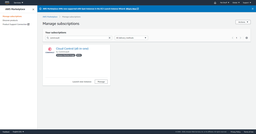
The Cloud Control is a Windows CommServe server installation. The first step needed is to open a PowerShell and connect to Amazon using the aws command line interface. This might require an Install-Module aws to get the aws command line installed and configured but once it is ready to connect to aws by typing in

aws configure

We can search for Marketplace images by doing an ec2 describe-images with a filter option

aws ec2 describe-images –executable-users all –filters “Name=name,Values=*Cloud Control*”

The describe-images command searches for an Amazon AMI that matches the description that we are looking for and returns an AMI ID. From this we can create a new instance pre-configured with a CommServe server. From here we can create out terraform files. It is important to note that the previous examples of main.tf and network.tf files do not need to be changed for this definition. We only need to create a virtual_machine.tf file to define our instance and have it created with the network configurations that we have previously defined.

We will need to create a new variable in our main.tf file that defines the private and public key that we are going to use to authenticate against our Windows server.

resource “aws_key_pair” “cmvlt2020” {
provider = aws.east
key_name = “cmvlt2020”
public_key = “AAAAB3NzaC1yc2EAAAADAQABAAABAQCtVZ7lZfbH8ZKC72A+ipNB6L/upQrj8pRxLwzQi7LVPrameil8/q4ROvWbC1KC9A3Ego”
}

A second element that needs to be defined is an aws_ami data declaration to reference an existing AMI. This can be done in the virtual_machines.tf file to isolate the variable and data declaration for virtual machine specific definitions. If we wanted to define an Ubuntu instance we would need to define the owner as well as the filter to use for an aws_ami search. In this example we are going to look for Ubuntu on an AMD 64-bit processor. The unusualness is the owners that needs to be used for Ubuntu since it is controlled by a third part Marketplace owner.

variable “ubuntu-version” {
type = string
default = “bionic”
# default = “xenial”
# default = “groovy”
# default = “focal”
# default = “trusty”
}

data “aws_ami” “ubuntu” {
provider = aws.east
most_recent = true
# owners = [“Canonical”]
owners = [“099720109477”]
filter {
name = “name”
values = [“ubuntu/images/hvm-ssd/ubuntu-${var.ubuntu-version}–amd64-server-“]
}
}

output “Ubuntu_image_name” {
value = “${data.aws_ami.ubuntu.name}”
}

output “Ubuntu_image_id” {
value = “${data.aws_ami.ubuntu.id}”
}

In this example we will be pulling the ubuntu-bionic-amd64-server image that has hardware virtualization running on a solid state disk. The variable ubuntu-version is mapped to the version of the Ubuntu kernel that is desired. The filter.values does the search in the Marketplace store to find the AMI ID. We restrict the search by searching in the region that we are deploying and use owner “099720109477” as the Marketplace provider.

If we compare this to a CentOS deployment the centos-version variable has a different string definition and a different owner.

variable “centos-version” {
type = string
default = “Linux 7 x86_64”
# default = “Linux 6 x86_64”
}

data “aws_ami” “centos” {
provider = aws.east
most_recent = true
owners = [“aws-marketplace”]

filter {
name = “name”
values = [“CentOS ${var.centos-version}*”]
}
}

output “CentOS_image_name” {
value = “${data.aws_ami.centos.name}”
}

output “CentOS_image_id” {
value = “${data.aws_ami.centos.id}”
}

For CentOS we can deploy 6 or version 7 by changing the centos-version.default definition. It is important to note that the owner of this AMI is not Amazon and uses the aws-marketplace definition to perform the filter. The same is true for the Commvault image that we are looking at.

data “aws_ami” “commvault” {
provider = aws.east
most_recent = true
# owners = [“Canonical”]
owners = [“aws-marketplace”]

filter {
name = “name”
values = [“*Cloud Control*”]
}
}

output “Commvault_CommServe_image_name” {
value = “${data.aws_ami.commvault.name}”
}

output “Commvault_CommServe_image_id” {
value = “${data.aws_ami.amazon.id}”
}

Note the filter uses a leading wildcard with the name “Cloud Control” followed by a wildcard to look for the instance that we are looking for. Once we have the AMI we can use the AMI.id from our search to define the aws_instance definition.

resource “aws_instance” “commserve” {
provider = aws.east
ami = data.aws_ami.commvault.id
associate_public_ip_address = true
instance_type = “m5.xlarge”
key_name = “cmvlt2020”
vpc_security_group_ids = [aws_security_group.cmvltRules.id]
subnet_id = aws_subnet.mySubnet.id
tags = {
Name = “TechEnablement test”
environment = var.environment
createdby = var.createdby
}
}

output “test_instance” {
value = aws_instance.commserve.public_ip
}

If we take the aws_instance declaration piece by piece the provider defines which AWS region that we will provision into Amazon. The vpc_security_group_ids and subnet_id defines what network that this instance will join. The new declarations are

  • ami – AWS AMI id to use as the source to clone
  • associate_public_ip_address – do we want a public or private only IP address with this instance
  • instance_type – this is the size. We need to reference the documentation or our users to figure out how large or how small this server needs to be. From the Commvault documentation the smallest recommended size is an m5.xlarge.
  • key_name – this is the public and private key names that will be used to connect to the Windows instance.

The remainder of the variables like disk, is this a Windows instance, and all the regular required parameters we saw with a vsphere_virtual_machine are provided by the AMI definition.

With these files we can execute from the following files

  • aws configure
  • terraform init
  • terraform plan
  • terraform apply

In summary, pulling an AMI ID from the marketplace works well and allows us to dynamically create virtual machines from current or previous builds. The terraform apply finishes quickly but the actual spin up of the Windows instance takes a little longer. Using Marketplace instances like the Commvault AMI provides a good foundation for a proof of concept or demo platform. The files used in this example are available in github.com.

AWS networking with Terraform

In our previous blog we talked about provisioning an AWS Provider into Terraform. It was important to note that it differed from the vSphere provider in that you can create multiple AWS providers for different regions and give an alias to each region or login credentials as desired. With vSphere you can only have one provider and no aliases.

Once we have a provider defined we need to create elements inside the provider. If our eventual goal is to create a database using software as a service or a virtual machine using infrastructure as a service then we need to create a network to communicate with these services. With AWS there are basically two layers of network that you can define and two components associated with these networks.

The first layer is the virtual private network which defines an address range and access rights into the network. The network can be completely closed and private. The network can be an extension of your existing datacenter through a virtual private network connection. The network can be an isolated network that has public access points allowing clients and consumers access to websites and services hosted in AWS.

Underneath the virtual private network is either a public or private subnet that segments the IP addresses into smaller chunks and allows for instances to be addressed on the subnet network. Multiple subnet definitions can be created inside a virtual private network to segment communications with the outside world and private communications between servers (for example a database server and applications server). The application server might need a public IP address and an private IP address while the database server typically will only have a private IP address.

Associated with the network and subnets are a network security group and internet gateway to restrict access to servers in the AWS cloud. A diagram of this configurations with a generic compute instance is shown below.

The first element that needs to be defined is the AWS Provider.

provider “aws” {
version = “> 2”
profile = “default”
region = “us-east-1”
alias = “east”
}

The second component would be the virtual private cloud or aws_vpc.

resource “aws_vpc” “myNet” {
cidr_block = “10.0.0.0/16”
provider = aws.east
tags = {
Name = “myNet”
environment = var.environment
createdby = var.createdby
}
}

Note that the only required attribute for the aws_vpc is the cidr_block. Everything else is optional. It is important to note that the aws_vpc can be defined as a resource or as a data element that does not create or destroy the network definition in AWS with terraform apply and destroy. With the data declaration the cidr_block is optional given that it has already been defined and the only only attribute needed to match the existing VPC is the name or the ID of the existing VPC.

Once the VPC has been created an aws_subnet can be defined and the two required elements for a resource definition are the cidr_block and the vpc_id. If you want to define the aws_subnet as a data element the only required resource is the vpc_id.

resource “aws_subnet” “MySubnet” {
provider = aws.east
vpc_id = aws_vpc.myNet.id
cidr_block = “10.0.1.0/24”
tags = {
Name = “MySubnet”
environment = var.environment
createdby = var.createdby
}
}

The provider declaration is not required but does help with debugging and troubleshooting at a later date. It is important to note that the VPC was defined with a /16 cidr_block and the subnet was a more restrictive /24 cidr_block. If we were going to place a database in a private network we would create another subnet definition and use a different cidr_block to isolate the network.

Another element that needs to be defined is an aws_internet_gateway to define access from one network (public or private) to another network. The only required element that is needed for the resource declaration is the internet gateway id. If you define the aws_internet_gateway as a data declaration then the name or the vpc_id is required to map to an existing gateway declaration.

resource “aws_internet_gateway” “igw” {
provider = aws.aws
vpc_id = aws_vpc.myNet.id
tags = {
Name = “igw”
environment = var.environment
createdby = var.createdby
}
}

The final element that we want to define is the network security group which defines ports that are open inbound and outbound. In the following example we define inbound rules for ports 80, 443, and 8400-8403, ssh (port 22), and rdp (port 3389) as well as outbound traffic for all ports.

resource “aws_security_group” “cmvltRules” {
provider = aws.aws
name = “cmvltRules”
description = “allow ports 80, 443, 8400-8403 inbound traffic”
vpc_id = aws_vpc.myNet.id

ingress {
description = “Allow 443 from anywhere”
from_port = 443
to_port = 443
protocol = “tcp”
cidr_blocks = [“0.0.0.0/0”]
}

ingress {
description = “Allow 80 from anywhere”
from_port = 80
to_port = 80
protocol = “tcp”
cidr_blocks = [“0.0.0.0/0”]
}

ingress {
description = “Allow 8400-8403 from anywhere”
from_port = 8400
to_port = 8403
protocol = “tcp”
cidr_blocks = [“0.0.0.0/0”]
}

ingress {
description = “Allow ssh from anywhere”
from_port = 22
to_port = 22
protocol = “tcp”
cidr_blocks = [“0.0.0.0/0”]
}

ingress {
description = “Allow rdp from anywhere”
from_port = 3389
to_port = 3389
protocol = “tcp”
cidr_blocks = [“0.0.0.0/0”]
}

egress {
description = “Allow all to anywhere”
from_port = 0
to_port = 0
protocol = “-1”
cidr_blocks = [“0.0.0.0/0”]
}

tags = {
Name = “cmvltRules”
environment = var.environment
createdby = var.createdby
}

}

For the security group the protocol and from_port are the only required definitions when defining an aws_security_group resource. If you declare an aws_security_group data declaration then the name is the only required element. For the declaration shown above the provider and vpc_id to help identify the network that the roles are associated with for debugging and troubleshooting.

This simple video looks at the AWS console to see the changes defined by terraform using the main.tf and network.tf files saved in github.com.
In summary, network definitions on AWS are radically different and more secure than a typical vSphere provider definition with undefined network configurations. Understanding network configurations in Terraform help build a more predictable and secure deployment in the cloud. If you are part of a larger organization you might need to use data declarations rather than resource declarations unless you are creating your own sandbox. You might need to join a corporate VPC or dedicated subnet assigned to your team. Once networking is defined, new and creating things like moving dev/test to the cloud or testing database as a service to reduce license costs. The only step missing from these configuration files are setting up the aws configure and authentication using the AWS CLI interface. Terraform does a good job leveraging the command line authentication so that the public and private keys don’t need to be stored in files or configuration templates.
aws provider vs vsphere provider

In a previous post we talked about the vsphere provider and what is needed to define a connection to create a virtual machine. In this blog we will start to look at what is needed to setup a similar environment to do the same thing in AWS EC2. Think of it as a design challenge. Your client comes to you and says “I want a LAMP or WAMP stack or Tomcat Server that I can play with. I want one local as well as one in the cloud. Can you make that happen?”. You look around and find out that they do have a vSphere server and figure out how to log into it and create a Linux instance to build a LAMP stack and a Windows instance to create a WAMP stack then want to repeat this same configuration in AWS, Azure, and/or Google GCP. Simple, right?

If you remember, to create a vSphere provider declaration in Terraform you basically need a username, password, and IP address of the vSphere server.

provider “vsphere” {
user = var.vsphere_user
password = var.vsphere_password
vsphere_server = var.vsphere_server
version = “1.12.0”

allow_unverified_ssl = true
}

The allow_unverified_ssl is to get around that most vSphere installations in a lab don’t have a certified certificate but a self-signed certificate and the version is to help us keep control of syntax changes in our IaC definitions that will soon follow.

The assumptions that you are making when connecting to a vSphere server when you create a virtual machine are

  1. Networking is setup for you. You can connect to a pre-defined network interface from vSphere but you really can’t change your network configuration beyond what is defined in your vSphere instance.
  2. Firewalls, subnets, and routing is all defined by a network administrator and you really don’t have control over the configuration inside Terraform unless you manage your switches and routers from Terraform as well. The network is what it is and you can’t really change it. To change routing rules and blocked or open ports on a network typically requires reconfiguration of a switch or network device.
  3. Disks, memory, and CPUs are limited by server configurations. In my home lab, for example, I have two 24 core servers with 48 GB of RAM on one system and 72 GB of RAM on the other. One system has just under 4 TB of disk while the other has just over 600 GB of disk available.
  4. Your CPU selection is limited to what is in your lab or datacenter. You might have more than just an x86 processer here and there but the assumption is that everything is x86 based and not Sparc or PowerPC. There might be an ARM processor as an option but not many datacenters have access to this unless they are developing for single board computers or robotics projects. There might be more advanced processors like a GPU or Nvidia graphics accelerated processor but again, these are rare in most small to midsize datacenters.

Declaring a vsphere provider gives you access to all of these assumptions. If you declare an aws or azure provider these assumptions are not true anymore. You have to define your network. You can define your subnet and firewall configurations. You have access to almost unlimited CPU, memory, and disk combinations. You have access to more than just an x86 processor and you have access to multiple datacenters that span the globe rather than just a single cluster of computers that are inside your datacenter.

The key difference between declaring a vsphere provider and an aws provider is that you can declare multiple aws providers and use multiple credentials as well as different regions.

provider “aws” {
version = “> 2”
profile = “default”
region = “us-east-1”
alias = “aws”
}

Note we don’t connect to a server. We don’t have a username or password. We do define a version and have three different parameters that we pass in. So the big question becomes how do we connect and authenticate? Where is this done if not in the provider connection? We could have gotten by with just provider “aws” {} and that would have worked as well.

To authenticate using the Hashicorp aws provider declaration you need to

  • declare the access_key and secret_key in the declaration (not advised)
  • declare the AWS_ACCESS_KEY_ID and AWS_SECRET_ACCESS_KEY_ID as environment variables
  • or point to a configuration file with the shared_credentials_file declaration or AWS_SHARED_CREDENTIALS_FILE environment variable leveraging the profile declaration or PROFILE environment variable.
  • automatic loading of the ~/.aws/credentials or ~/.aws/config files

The drawback to using the environment variables is that you can only have one login into your aws console but can connect to multiple regions with the same credentials. If you have multiple accounts you need to declare the access_key and secret_key or the more preferred method of using the shared_credentials_file declaration.

For the aws provider, all parameters are optional. The provider is flexible enough to make some assumptions and connect to AWS based on environment variables and optional parameters defined. If something is defined with a parameter it is used over the environment variable. If you define both a key and a shared_credentials_file, Terraform will throw an error. If you have environment variables define and a ~/.aws/credentials file, the environment variables will be used first.

If we dive a little deeper into our vsphere variables.tf file we note that we need to run a script or manually generate the declarations for vsphere_datacenter, vsphere_host, and vsphere_resource_pool prior to defining a virtual machine. With the aws provider we only need to define the region to define all of these elements. Unfortunately, we also need to define the networking connections, subnet definitions, and potential firewall exceptions to be able to access our new virtual machine. It would be nice if we could take our simple vsphere virtual machine definition defined in our vsphere main.tf file and translate it directly into an aws_instance declaration. Unfortunately, there is very little that we can translate from one environment to the other.

The aws provider and aws_instance declaration does not allow us to clone an existing instance. We need to go outside of Terraform and create an AMI to use as a reference for aws_instance creation. We don’t pick a datacenter and resource_pool but select a region to run our instance. We don’t need to define a datastore to host the virtual machine disks but we do need to define the disk type and if it is a high speed (higher cost) or spinning disk (lower cost) to host the operating system or data.

We can’t really take our existing code and run it through a scrubber and spit out aws ready code unfortunately. We need to know how to find a LAMP, WAMP, and Tomcat AMI and reference it. We need to know the network configurations and configure connections to another server like a database or load balancer front end. We also need to know what region to deploy this into and if we can run these services using low cost options like spot instances or can shut off the running instance during times of the day to save money given that a cloud instance charges by the minute or hour and a vsphere instance is just consuming resources that you have already paid for.

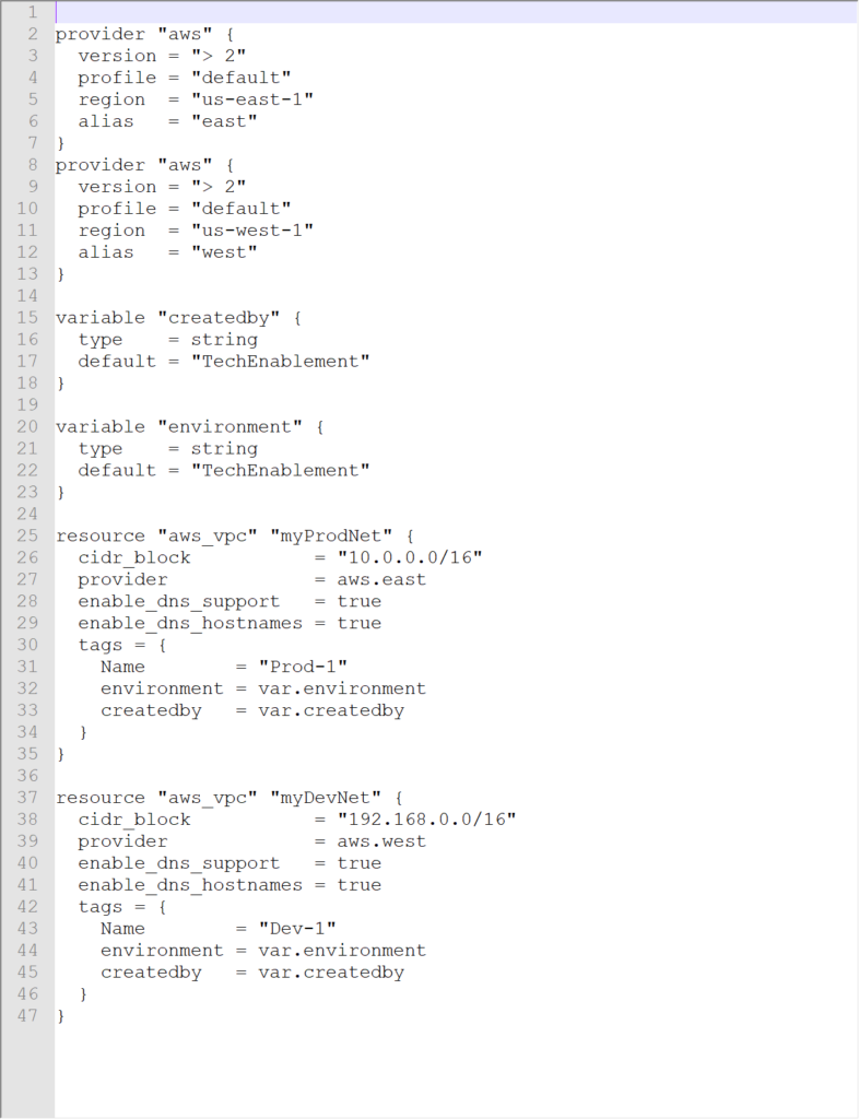
One of the nice things about an aws provider declaration is that you can define multiple providers in the same file which generated an error for a vsphere provider. You can reference different regions using an alias. In the declaration shown above we would reference the provider with

provider = aws.aws

If we wanted to declare that the east was our production site and the west was our dev site we could use the declaration

provider “aws” {
version = “> 2”
profile = “default”
region = “us-east-1”
alias = “east”
}
provider “aws” {
version = “> 2”
profile = “default”
region = “us-west-1”
alias = “west”
}

If we add a declaration of a network component (aws_vpc) we can populate our state file and see that the changes were pushed to our aws account.

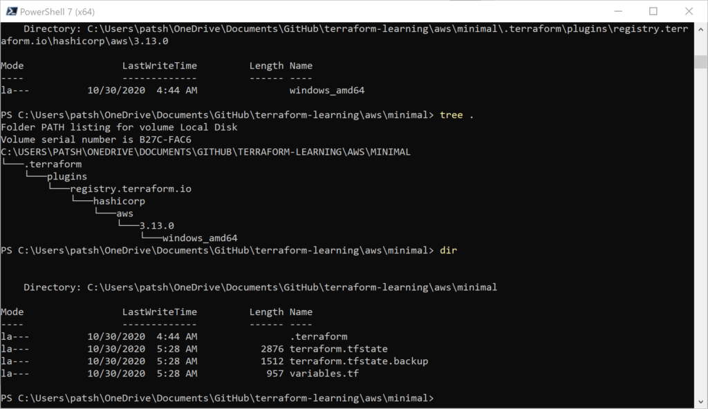
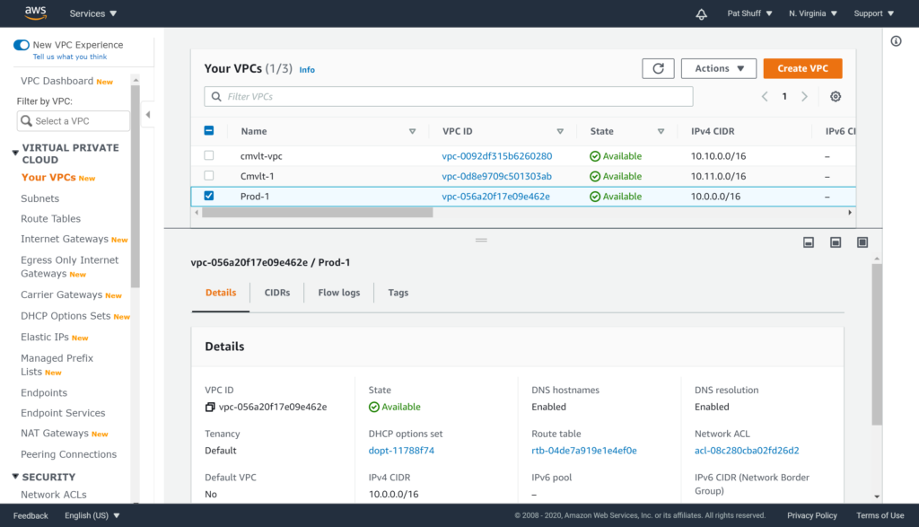
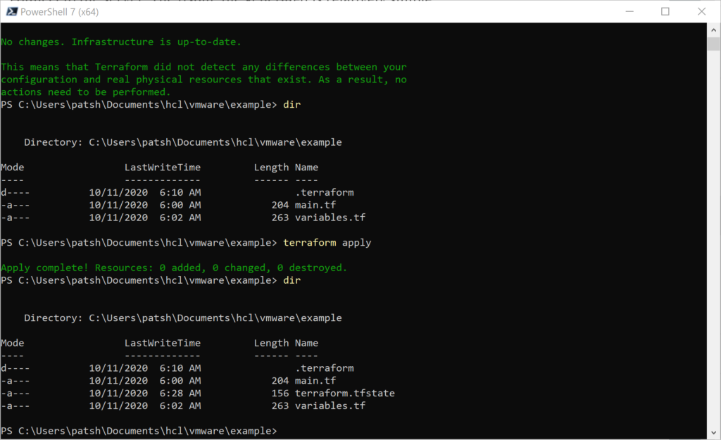
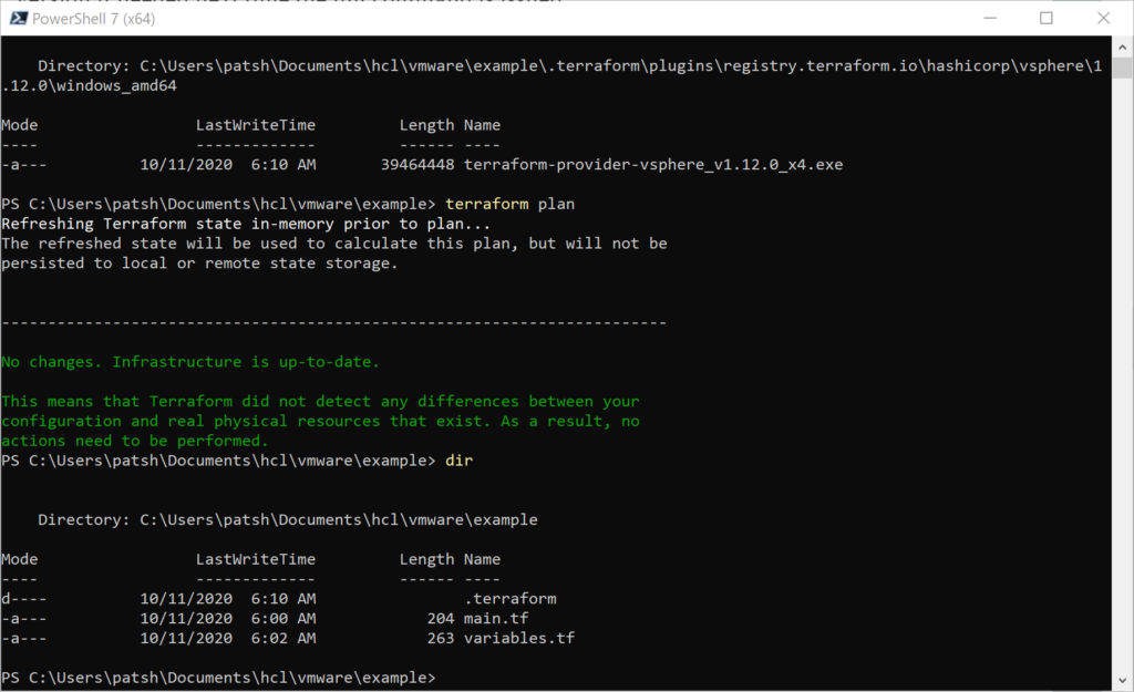
We get the .terraform tree populated for our Windows desktop environment as well as the terraform.tfstate created. Looking at our AWS VPC console we see that Prod-1 was created in US-East-1 (and we could verify that Dev-1 was created in US-West-1 if we wanted).

Note that the CIDR block was correctly defined as 10.0.0.0/16 as desired. If we run the terraform destroy command to clean up this vpc will be destroyed since it was created and is controlled by our terraform declaration.

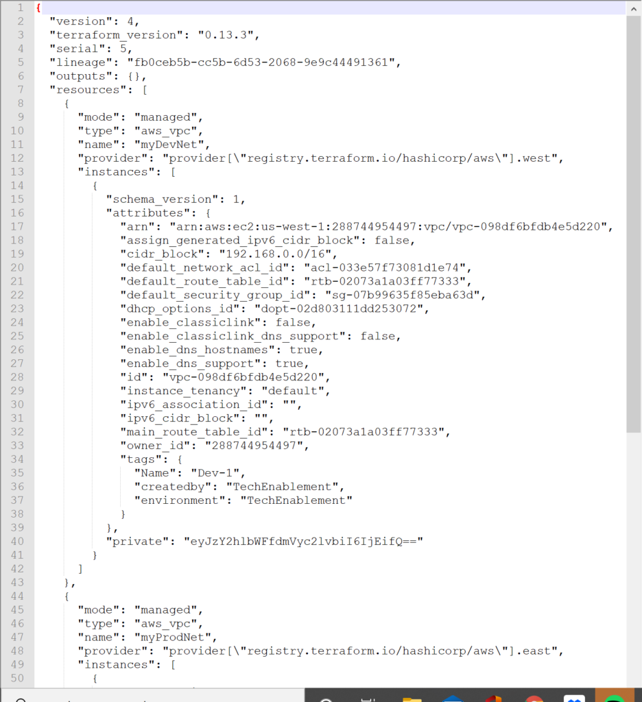
Looking at our terraform state file we can see that we did create two VPC instances in AWS and the VPC ID should correspond to what we see in the AWS console.

In summary, using Terraform to provision and manage resources in Amazon AWS is somewhat easier and somewhat harder than provisioning resources in a vSphere environment. Unfortunately, you can’t take a variables.tf or main.tf declaration from vSphere and massage it to become a AWS definition. The code needs to be rewritten and created using different questions and parameters. You don’t need to get down to the SCSI target level with AWS but you do need to define the network connection and where and how the resource will be declared with a finer resolution. You can’t clone an existing machine inside of Terraform but you can do it leveraging private AMI declarations in AWS similar to the way that templates are created in vSphere. Overall an AWS managed state with Terraform is easy to start and allows you to create a similar environment to an on-premises environment as long as you understand the differences and cost implications between the two. Note that the aws provider declaration is much simpler and cleaner than the vsphere provider. Less is needed to define the foundation but more is needed as far as networking and how to create a virtual instance with AMIs rather than cloning.

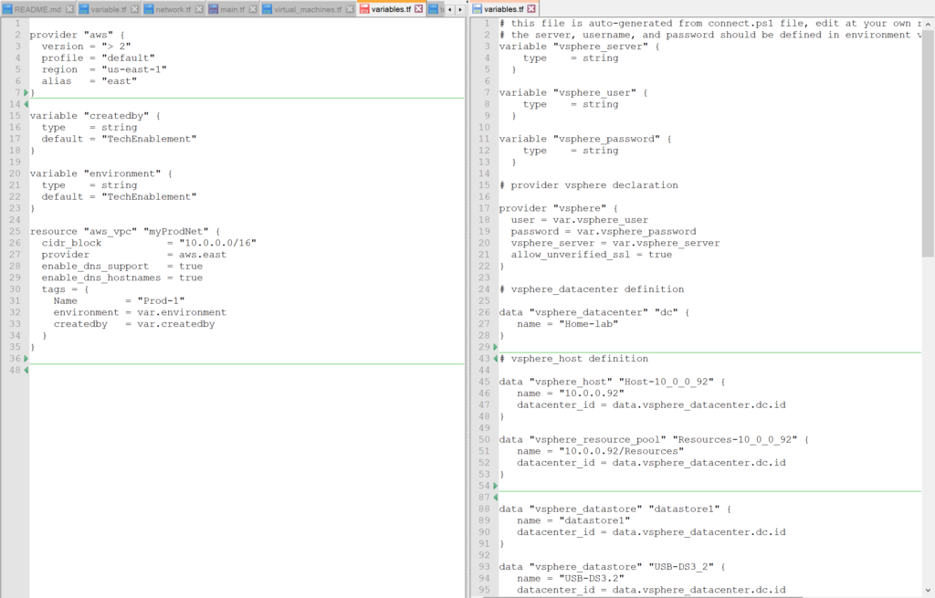
The variables.tf and terraform.state files are available on github to review.

vsphere_virtual_machine creation

In a previous blog we looked at how to identify an existing vSphere virtual machine and add it as a data element so that it can be referenced. In this blog we will dive a little deeper and look at how to define a similar instance as a template then use that template to create a new virtual machine using the resource command.

It is important to note that we are talking about three different constructs within Terraform in the previous paragraph.

  • data declaration – defining an existing resource to reference it as an element. This element is considered to be static and can not be modified or destroyed but it does not exist, terraform will complain that the declaration failed since the element does not exist. More specifically, data vsphere_virtual_machine is the type for existing vms.
  • template declaration – this is more of a vSphere and not necessarily a Terraform definition. This defines how vSphere copies or replicates an existing instance to create a new one as a clone and not necessarily from scratch
  • resource declaration – defining a resource that you want to manage. You can create, modify, and destroy the resource as needed or desired with the proper commands. More specifically, resource vsphere_virtual_machine is the type for new or managed vms.

We earlier looked at how to generate the basic requirements to connect to a vSphere server and how to pull in the $TF_VAR_<variable> label to connect. With this we were able to define the vspher_server, vsphere_user, and vspher_password variable types using a script. If we use the PowerCLI module we can actually connect using this script using the format

Connect-VIServer -Server $TF_VAR_vsphere_server -User $TF_VAR_vsphere_user -Password $TF_VAR_vsphere_password

This is possible because if the values do not exist then they are assigned in the script file. From this we can fill in the following data

  • vsphere_datacenter from Get-Datacenter
  • vsphere_virtual_machine (templates) from Get-Template
  • vsphere_host from Get-Datacenter | Get-VMHost
  • vsphere_datastore from Get-Datastore

The vsphere_datacenter assignment is relatively simple

$connect = Connect-VIServer -Server $TF_VAR_vsphere_server -User $TF_VAR_vsphere_user -Password $TF_VAR_vsphere_password

$dc = Get-Datacenter
Write-Host ‘# vsphere_datacenter definition’
Write-Host ‘ ‘
Write-Host -Separator “” ‘data “vsphere_datacenter” “dc” {
name = “‘$dc.Name'”‘
‘}’
Write-Host ‘ ‘

This results in an output that looks like…

# vsphere_datacenter definition

data “vsphere_datacenter” “dc” {
name = “Home-lab”
}

This is the format that we want for our parameter.tf file. We can do something similar for the vm templates

Write-Host ‘# vsphere_virtual_machine (template) definition’
Write-Host ‘ ‘
$Template_Name = @()
$Template_Name = Get-Template

foreach ($item in $Template_Name) {
Write-Host -Separator “” ‘data “vsphere_virtual_machine” “‘$item'”‘ ‘ {
name = “‘$item'”‘
‘ datacenter_id = data.vsphere_datacenter.dc.id
}’
Write-Host ‘ ‘
}
Write-Host ‘ ‘

This results in the following output…

#vsphere_virtual_machine (template) definition

data “vsphere_virtual_machine” “win_10_template” {
name = “win_10_template”
datacenter_id = data.vsphere_datacenter.dc.id
}

data “vsphere_virtual_machine” “win-2019-template” {
name = “win-2019-template”
datacenter_id = data.vsphere_datacenter.dc.id
}

We can do similar actions for vsphere_host using

$Host_name = @()
$Host_name = Get-Datacenter | Get-VMHost

as well as vsphere_datastore using

$Datastore_name = @()
$Datastore_name = Get-Datastore

The resulting output is a terraform ready parameter file that represents the current state of our environment. The datacenter, host, and datastores should not change from run to run. We might define new templates so these might be added or removed but this script should be good for generating the basis of our existing infrastructure and give us the foundation to build a new vsphere_virtual_machine.

To create a vsphere_virtual_machine we need the following elements

  • name
  • resource_pool_id
  • disk
    • label
  • network_interface
    • network_id

These are the minimum requirements required by the documentation and will allows you to pass the terraform init but the apply will fail. Additional values that are needed

  • host_system_id – host to run the virtual machine on
  • guest_id – identifier for operating system type (windows, linux, etc)
  • disk.size – size of disk
  • clone.template_uuid – id of template to clone to create the instance.

The main.tf file that works to create our instance looks like

data “vsphere_virtual_machine” “test_minimal” {
name = “esxi6.7”
datacenter_id = data.vsphere_datacenter.dc.id
}

resource “vsphere_virtual_machine” “vm” {
name = “terraform-test”
resource_pool_id = data.vsphere_resource_pool.Resources-10_0_0_92.id
host_system_id = data.vsphere_host.Host-10_0_0_92.id
guest_id = “windows9_64Guest”
network_interface {
network_id = data.vsphere_network.VMNetwork.id
}
disk {
label = “Disk0”
size = 40
}
clone {
template_uuid = data.vsphere_virtual_machine.win_10_template.id
}
}

The Resources-10_0_0_92, Host-10_0_0_92, and win_10_template were all generated by our script and we pulled them from the variables.tf file after it was generated. The first vm “test_minimal” shows how to identify an existing virtual_machine. The second “vm” shows how to create a new virtual machine from a template.

The files of interest in the git repository are

  • connect.ps1 – script to generate variables.tf file
  • main.tf – terraform file to show example of how to declare virtual_machine using data and resource (aka create new from template)
  • variables.tf – file generated from connect.ps1 script after pointing to my lab servers

All of these files are located on https://github.com/patshuff/terraform-learning. In summary, we can generate our variables.tf file by executing a connext.ps1 script. This script generates the variables.tf file (test.yy initially but you can change that) and you can pull the server, resource_pool, templates, and datastore information from this config file. It typically only needs to be run once or when you create a new template if you want it automatically created. For my simple test system it took about 10 minutes to create the virtual machine and assign it a new IP address to show terraform that the clone worked. We could release earlier but we won’t get the IP address of the new virtual instance.